What is a photo relay for street lighting and how does it work
The device and principle of operation
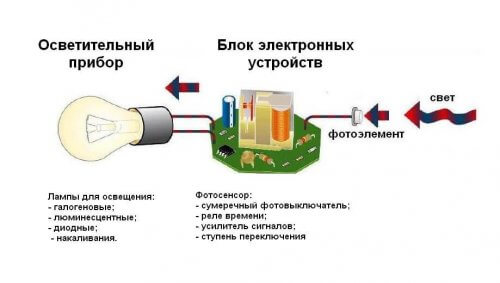
The device and the principle of operation of light relays are easier to understand after meeting with their constituent elements. Modern photorelay samples contain the following main parts:
- Sensitive photocell.
- A threshold comparator having a modular design, usually in the form of a separate microcircuit with a strapping, less often on discrete elements.
- A switching or, as it is also called, a power element (the relay itself or triacwhich includes the load).
As a sensor or photocell used photoresistorsphototransistors or typical photodiodes. The schemes usually provide for their analog inclusion with the ability to respond to gradations in the level of ambient light (sensitivity). To understand how this device works, just familiarize yourself with its internal device. The design of the photocells is such that when light enters the sensitive area, their electrical conductivity changes.
A description of the changes that occur in the device circuit in each case will help to understand the principle of operation of the photo relay. They look like this:
- Deviation of conductivity from the normal value is recorded by an electronic module configured to work with a photosensitive sensor.
- This node performs the function of a comparator, which turns on only when the lighting reaches a certain level (threshold).
- After that, the control unit (comparator) issues a control signal to the executive module, which disconnects the lighting devices from the power source.
As the executive unit, electronic circuits are used, assembled on the basis of transistor switches and powered by a low voltage of 12 volts. But in each specific device, the circuitry may differ.
After triggering, the photo relay goes into an off state, which remains until dark. With its arrival, the resistance of the conductive part of the sensitive element changes again, which leads to the re-inclusion of the comparator and the supply of a control signal to the executive module. The device connects 220 Volts to the lighting line and goes into standby mode for the next operation time.
This video demonstrates how to make a photo relay with your own hands, we also wrote a separate article about it: https://our.electricianexp.com/en/kak-sdelat-fotorele.html. Check out for a better understanding of the topic:
Wiring diagrams
The order of inclusion of the photo relay in the power circuit depends on the specific conditions of its operation. There are two known options for connecting the device to an existing mains:
- through the junction box;
- directly to the load line protected by the machine.
The electrical circuit diagram of the first of these connections is no different from a similar approach when organizing the switching of a light switch. The phase wire from the photo relay is connected to a free terminal of the distributor, and then with a jumper it switches to the corresponding branch of supplying voltage to the lighting device.
If there is no junction box in the single-line circuit of the facility, the device is connected directly to zero and phase. In this case, the following options for its exclusion are possible:
- Only the "phase" is started on the device, and the "zero" is laid bypass.
- Both the neutral and phase conductors used in the lighting switching circuit are connected to the terminals of the photo relay.
The first option is convenient when laying a new electrical wiring, when its route is chosen at its discretion. The use of the second method is justified in situations where the repair is already completed and it is undesirable to equip a new line (for this ditch the wall) In this case, the wires are laid in a separate plastic channel, laid from the light control device.
Types of relays and their symbols
The installation procedure for the photosensitive device depends on the type of product selected for lighting control. Before starting work, it is important to determine which relays are in the lighting circuits, and which of them is best suited for the stated purposes.
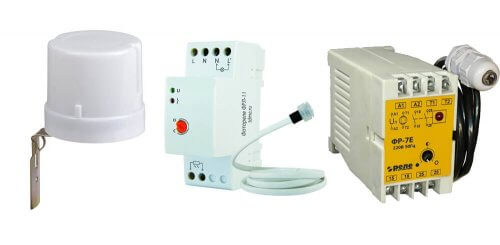
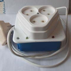
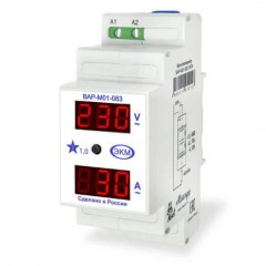
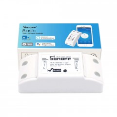
According to the installation method, the following types of photo relay are distinguished (listed according to the order in the figure below):
- Household devices for mounting on a solid horizontal surface.
- Models installed on DIN rail in the control cabinet (with remote sensor).
- Modular devices mounted in the entrance of an apartment building.
The main purpose of the devices in a modular design is the use in municipal enterprises, as well as in the maintenance of highway lighting networks and other facilities. They are installed in the electrical panel, which allows both to connect the load directly and to connect lighting through a contactorif the photocell power is not enough for the expected load.
Samples of modular relays are often mounted on DIN rails in cabinets of private facilities.
By the presence of additional options, the relay can be:
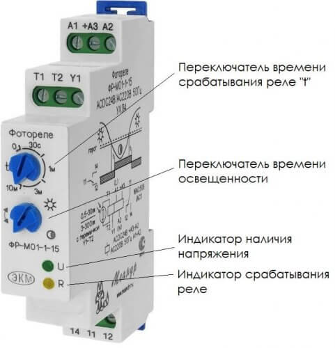
- Adjustable and unregulated, which means the possibility of setting its sensitivity.
- A device with a timer that sets a specific time for the light to turn on (off).
- Combined with a motion sensor that is triggered when a person moves in the field of his sensitivity.
- With time delay programmable as needed.
Sensitivity and other parameters are adjusted by means of the organs available on the device body.
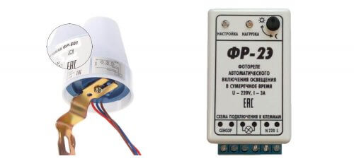
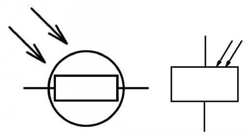
In addition, the samples of the lighting control relays differ by the manufacturer's brand, in accordance with which such models as FR-601 and the like are distinguished. In practice, there are often products of the old years of production (FR-2, for example). In addition to the fact that each photorelay sample has its own letter designation, they are represented in schemes in the form of conditional graphic symbols (UGO).
All of the listed devices have their own symbol on the diagram, presented in the form of typical icons. Usually this is a symbol of the most sensitive element (resistor, diode or transistor), with arrows pointing in its direction. A somewhat different way is represented by its symbol on the plan (in the form of a square with arrows).
Regardless of its purpose (for LED lamps, for example, or other purposes), before you buy a photo relay, you will need to carefully study their device. This will help to understand what it is from a technical point of view and significantly facilitate their operation. For those uninformed in technology, acquaintance with all the intricacies of the relay will allow you to understand what it does when implementing its functions.
We hope you now know how the photo relay works and what it is intended for. If you have any questions, ask them in the comments below the post!
Related materials:

