Scheme of connecting the spotlight to the sensor and photo relay
So, the first scheme for connecting an LED spotlight to a sensor is as follows: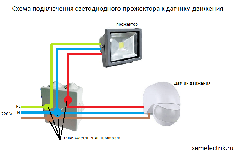
As you can see, three wires are connected to the junction box on the street: phase, ground, and zero. A PE wire (earth) is only needed if the lamp housing is metal. Everything is quite simple - the phase is conducted to break, zero to each device.
If you bought a touch lamp (the sensor is already installed in the housing), it is recommended to additionally connect it to the photo relay, which automatically turns on the light when dark. Here, the wiring of electrical wires is not very complicated: zero is output to each of the devices, the phase first goes to the photo relay, and then to the lamp.
Connection scheme of the touch spotlight with photo relay: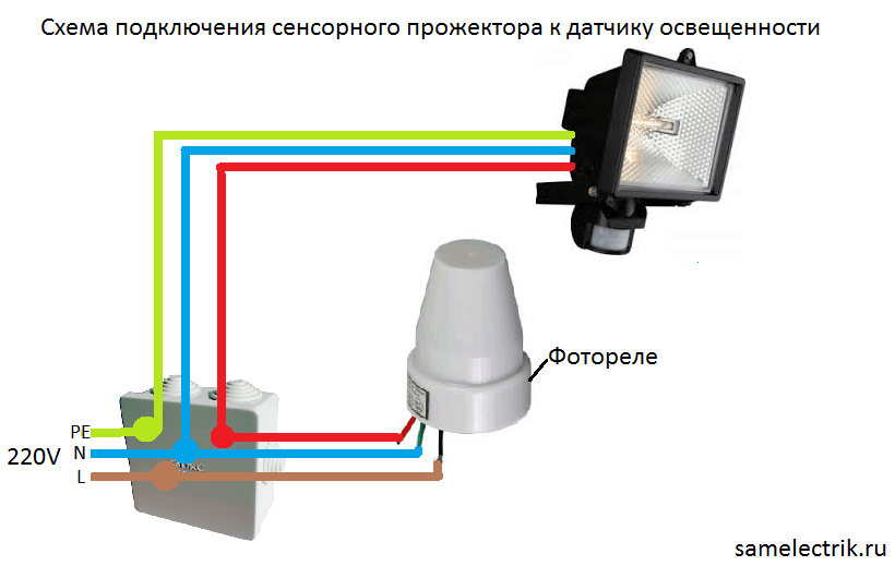
The principle of operation with this connection is as follows: when night falls, the photorelay closes the circuit, as a result of which current is supplied to the terminals of the halogen spotlight. As soon as a person appears in the detection zone, the sensor will react and close its section of the circuit, resulting in halogen lamp light up.
Well, the last option is suitable if you bought a simple LED spotlight (without a light and motion sensor). In this case, be sure to supplement the electrical circuit with two sensors connected in series, as shown below.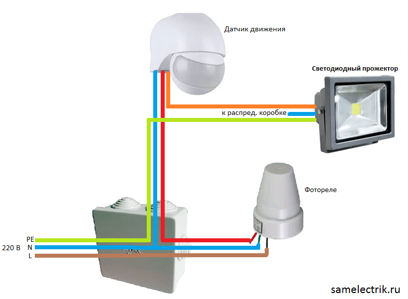
The last two connection options will make street lighting economical and fully automatic, so we recommend using one of them. If you bought a 12v lamp, then you need to connect it to the network only through a 220/12 Volt power supply. Connecting directly to the mains will damage the lamp.
That's all I wanted to tell you about this issue. As you can see, the connection diagram of the LED spotlight with motion sensor and photo relay is quite simple! Finally, we recommend that you connect the street lamp only through the machine, which will be installed in the switchboard on the street. This will allow for safe repair of the spotlight, as in these circuits only sensors are disconnected.
Similar materials:




The scheme is not correct. The red wire from the photo relay goes to the brown wire of the motion sensor, and not as in the picture.
The picture shows a conditional diagram. Everything about her is correct.
thanks, helped, according to your comment, and connect the remaining wires from the motion sensor red to the remaining wire from the spotlight brown and voila, the economical system works
The circuit does not match the description. According to the presented scheme, PE wire is indicated in the gap, and L should
Where did you see the PE wire break?