We connect the photo relay - step by step instructions with a video tutorial
The principle of operation of the device
So, first we’ll look at how the twilight switch works so that you can catch the features of its connection, which we will provide below.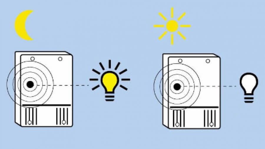
The design of the photo relay includes three main elements: a photocell, a comparator and a relay.
As for the photocell (and basically it is a photodiode, phototransistor or photoresistor), its main purpose is the analysis of light intensity. If the street begins to darken or lighten, the photocell will let you know about it, on the basis of which the light will turn on / off. The comparator is the so-called threshold of the system. If the voltage supplied by the photocell exceeds the setting, the comparator will turn on the relay, and accordingly the lamp. A relay (or triac) is an output device that switches the load (in our case, it is a light bulb).
Simply put, the principle of operation is this: with a decrease in the level of lighting, the resistance on the photoresistor changes, as a result of which the voltage rises and the relay operates. Result - the lamp to which the device is connected turns on until it starts to light.
Video review of the detector from the company Feron, model SEN27:
Wiring diagrams
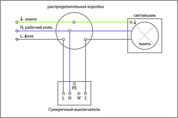
Before proceeding with the installation of a light control switch (another popular name) instead of a conventional light switch, you need to figure out how to connect the wires to the lamp and the sensor terminals. So, the connection scheme of the photo relay for street lighting can be presented in two versions: with the use of a junction box and without its use. The first option is usually used when home wiring replacementbecause In this case, you will need to output a new line from the mounting box.
As you can see, connecting the photo relay to the lamp is practically no different from connect light switch. As in the usual version, the phase is conducted to break, and zero is directly to the flashlight. The only difference is that the neutral wire must also be fed into the photosensor itself.
If you have already made repairs in the house and do not want to wall the wall under a new line, you can use the second option to connect the photo relay yourself - directly: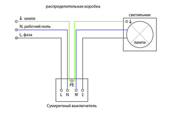
In this case, all 3 wires: phase, zero and ground are wound inside the case and are drawn in by the terminals. Both the first and second installation method is correct. Having chosen the appropriate option, you can proceed further - to install the photo relay yourself.
Step-by-step installation instructions
Immediately I would like to move a little away from the topic and advise you to simultaneously connect the photo relay and motion sensor for lighting. In a pair, these two devices will allow you to turn on the lamp when dark, only if a person appears in the detection zone. If no one is on the site, the bulbs will not light up, which will significantly save energy.
The installation method depends on what protection class and type of mounting the twilight light switch you bought.
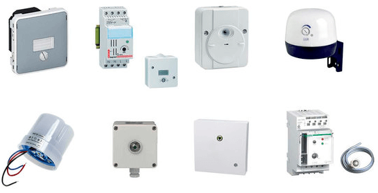
Today, there are various manufacturing options, namely:
- with mounting on a DIN rail, on a wall or on a horizontal surface;
- outdoor or indoor use (depending on IP protection class);
- photocell built-in or external.
In the instructions, we will provide for example the installation of a photo relay for street lighting with a wall mount. Connection is carried out at the stand for convenience, especially since this is just an example.
So, in order to connect the photo relay to the lamp yourself, you must follow these steps:
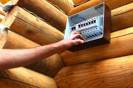
- We turn off the electricity on the input shield and check the presence of current in the junction box from which we will lead the wire.
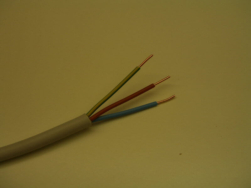
- We stretch the supply wire to the installation site of the photo relay (next to the lighting fixture). We recommend that you use a three-wire cable to connect the twilight switch PVA wire, which has established itself as a reliable and not too expensive version of the conductor.
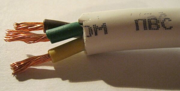
- We clean the conductors from insulation by 10-12 mm to connect them to the terminals.
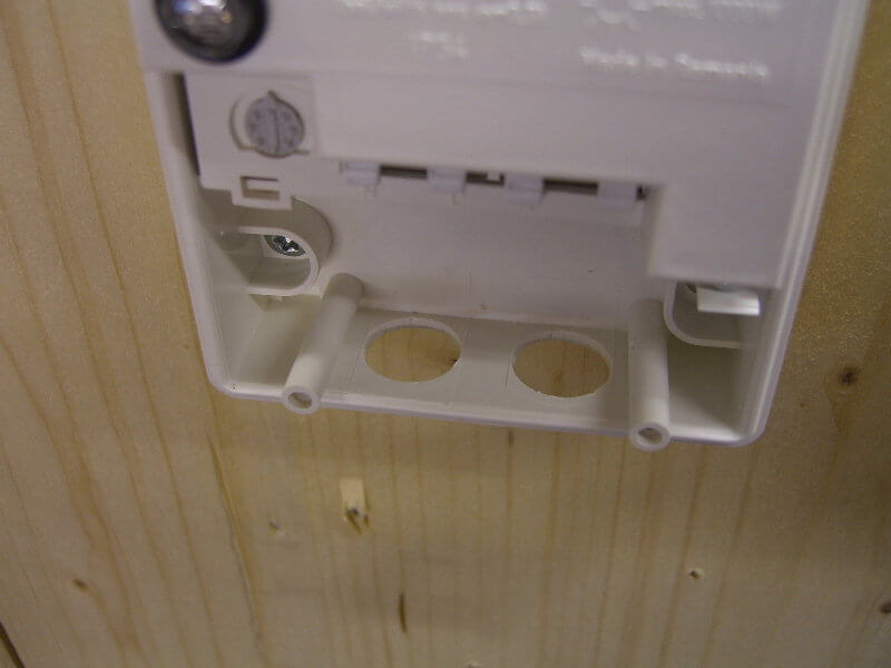
- We create holes in the housing for the institution of cores in order to connect the photo relay to the network and the lamp.
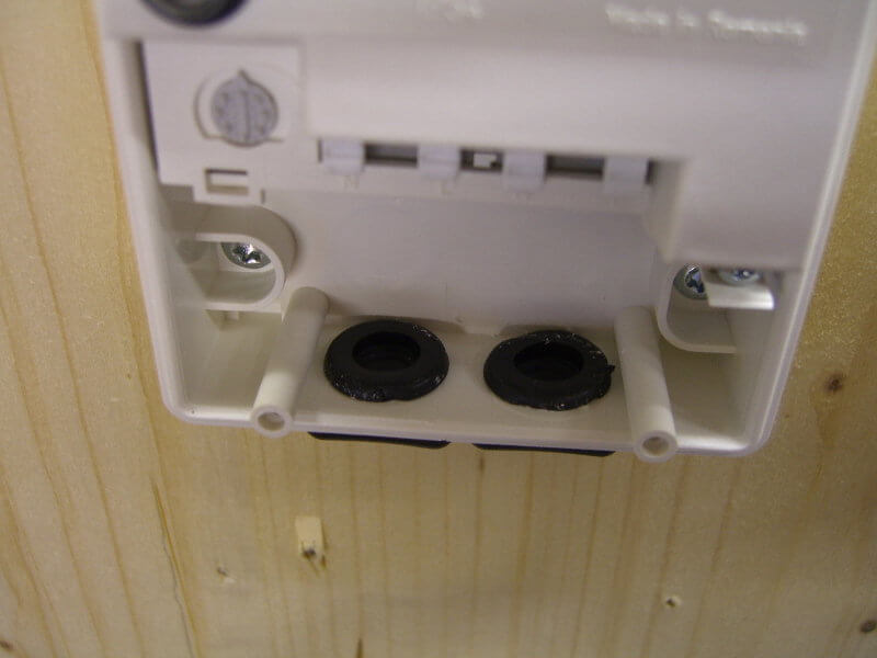
- To increase the tightness of the case, we fix special rubber seals in the cut-out holes that protect against ingress of dust and moisture inside. By the way, it is necessary to place the twilight switch so that the inlet openings are from below, which will prevent the penetration of moisture under the cover.
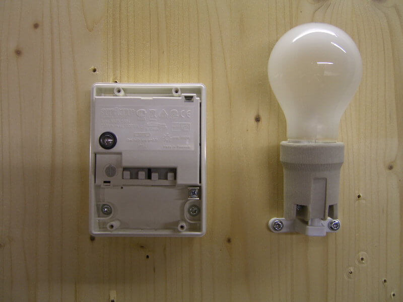
- We carry out the connection of the photo relay for street lighting according to the electrical circuit that we provided above. As you can see in the photo, the input phase is connected to the L connector, and the input neutral to N. A separate screw terminal with the corresponding designation is intended for grounding.
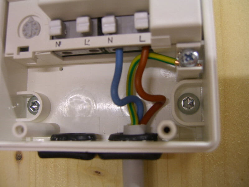
- We cut off the required length of the wire to connect the photo relay to the light bulb (in reality, it can even be an LED spotlight). We also clean the insulation by 10-12 mm and connect to the terminals N ’and L’, respectively. The second end of the conductor is brought to light source and attaching to the terminals of the cartridge. If the lamp housing does not conduct current, grounding is not necessary.
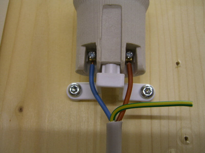
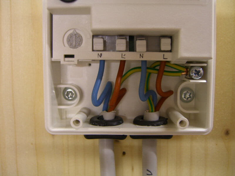
- Installation and connection are complete, go to do-it-yourself photo relay setup. There is nothing complicated, the kit contains a special black bag, which is necessary in order to imitate the night. On the body of the light sensor, you can see the regulator (signed by the abbreviation LUX), which serves to select the light intensity at which the relay will operate. If you want to save energy, set the rotary control to minimum (“-” mark). In this case, the power-on signal will be given in complete darkness on the street. Typically, the regulator is located next to the screw terminals, slightly to the left and above (as shown in the photo).

- The last step in connecting the photo relay is to attach the protective cover and turn on the power on the shield. Once you do this, you can proceed to testing the device.
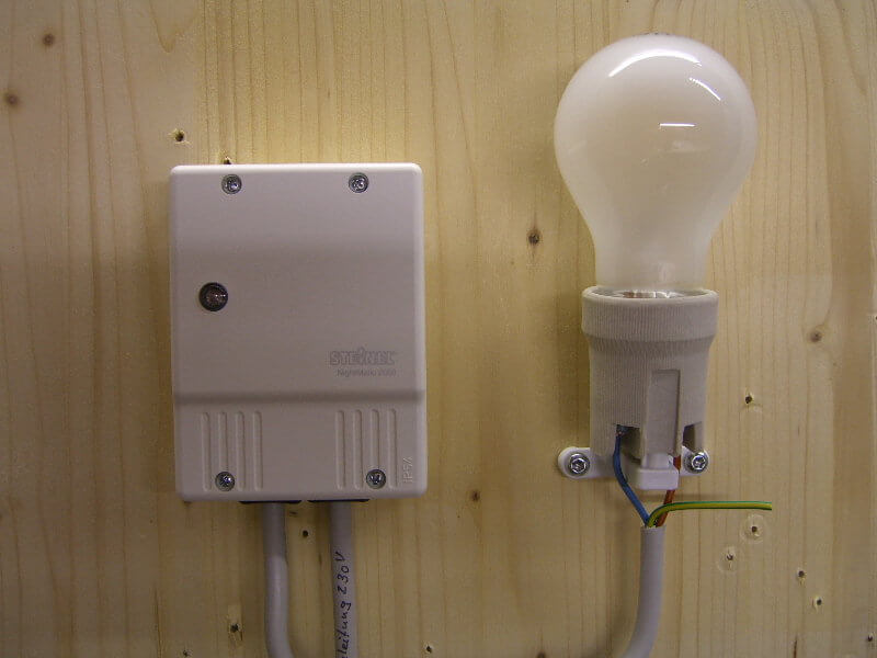
That's all I wanted to tell you about how to install and connect a photorelay with your own hands.We also recommend that you watch a visual video lesson in which the whole essence of wiring is shown in detail.
Finally, it should be said which manufacturers of twilight switches are the most high-quality. Today it is recommended to give preference to products from companies such as Legrand (Legrand), ABB, Schneider electric and IEK. By the way, the last company has a rather reliable model - FR-601, which has many positive reviews on the forums.
Related materials:





Tell me, is it possible to install the sensor on a lamp that is already standing on a pole? Zero goes directly to the wires and the phase through the switch. It turns out there is no zero which is needed for the sensor?
The sensor can be installed. Only connect to it you need zero necessarily.
We have 3 consecutive rooms (residential building corridor)
Room 1 there is daylight.
Room 2 (entrance) there is no daylight.
Room 3 is missing daylight.
Now there are 2 parallel-connected DD-024V in rooms 1 and 3.
Everything is working. I do not like that during the daytime in room 1, the light comes on.
I want to additionally put the photo relay FR 601 on the load of the room 1.
If power is supplied to the brown wire of the ФР 601 photo relay from A red DD-024V, how will the load (incandescent lamp) react when the motion sensor is triggered?
Is the circuit operational?
The circuit will work if you put a photo relay in front of the motion sensor in the first room. It is not necessary to connect the photo relay to the entire line, but only to the branch that goes to the first sensor. Those. the second motion sensor must not be dependent on the photo relay. Then the scheme of work will be as follows: the light in the first room will turn on only in the dark and only when the DD is triggered. In the third room, the light will always turn on when the DD is triggered. When you make the connection, unsubscribe whether everything works correctly, because We have never used such a scheme; it was compiled only in theory.
Room 1 - exit to the elevators and the stairwell.
Room 2 - Tambour - the passage space between the doors in which the waste bin is located.
Room 3 - corridor for 4 apartments.
The motion sensor DD 024V has a built-in light sensor.
To implement your connection scheme, it is enough to use the built-in light sensor and distribute the load separately for each DD. (on DD-1 the load of the room 1, on DD-2 the load of the room 3)
The problem with Room 2, where to connect?
If to DD-1, then the lighting in room 2 will not turn on when leaving the apartments.
If to DD-2, then the lighting in room 2 will not turn on when exiting the elevator.
Put another DD in room 2, it seems like it’s unprofitable.
Based on the above, and the idea arose, in addition to put the photo relay FR 601 on the load of the room 1.
I connected the photocell FR 601. The power comes from DD 024V.
Tested.
It works, but the lighting (in the dark) turns on 6 seconds after the DD 024V triggers.
I just have time in complete darkness to get from the elevator to the vestibule door. Inconveniently.
Will have to put another DD in room 2.
Give it a try! Waiting for the results!