A brief overview of the conventions used in wiring diagrams
Graphic
As for the graphic designation of all the elements used in the diagram, we will provide this review in the form of tables in which the products will be grouped by purpose.
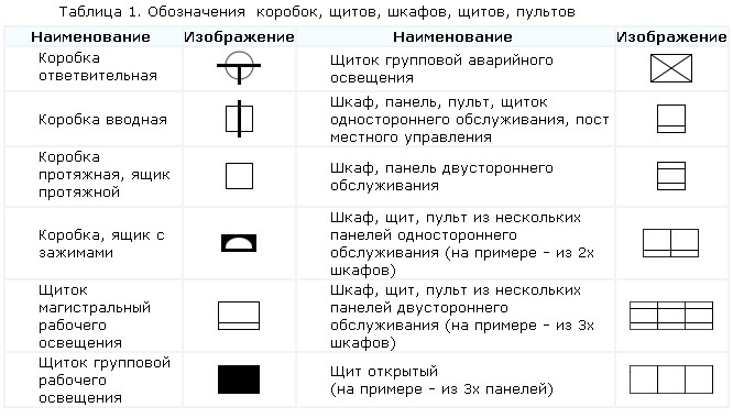
In the first table you can see how electrical boxes, panels, cabinets and remotes on electrical circuits are marked:
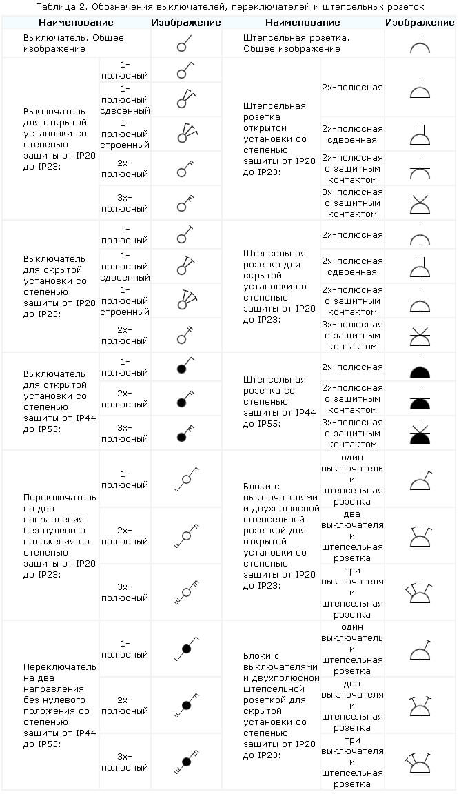
The next thing you should know is the symbol of the supply sockets and switches (including walk-throughs) on single-line schemes of apartments and private houses:
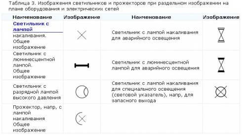
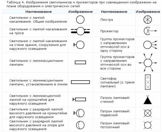
As for the lighting elements, fixtures and lamps according to GOST indicate as follows:
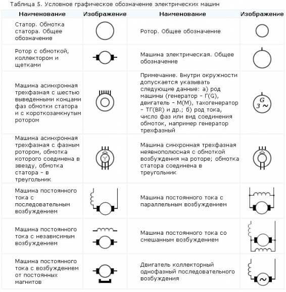
In more complex circuits where electric motors are used, elements such as:
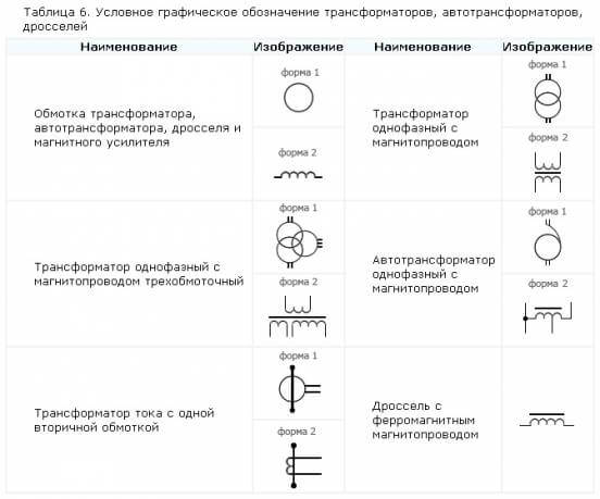
It is also useful to know how transformers and inductors are graphically indicated on principle circuit diagrams:
Electrical appliances in accordance with GOST have the following graphic designation in the drawings:
And here, by the way, is a table that is useful for beginning electricians, which shows what the ground loop looks like on the wiring plan, as well as the power line itself:
In addition to this, on the diagrams you can see a wavy or straight line, “+” and “-”, which indicate the type of current, voltage and pulse shape:
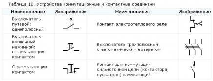
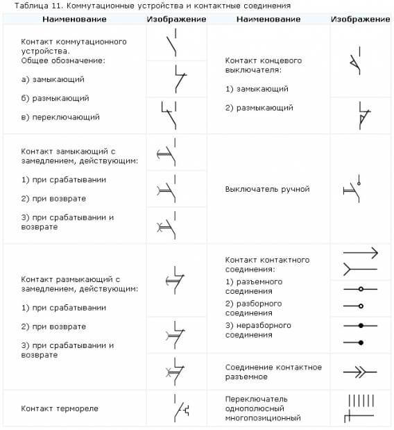
In more complex automation circuits, you may come across strange graphic notations, such as contact connections. Remember how these devices are indicated on electrical circuits:
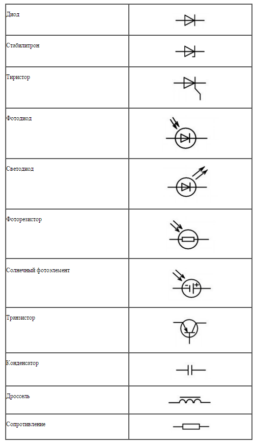
In addition, you should be aware of how radio elements look on projects (diodes, resistors, transistors, etc.):
That's all conventionally graphic designations in electrical circuits of power circuits and lighting. As you yourself have already seen, there are quite a few components and you can remember how each is designated only with experience. Therefore, we recommend that you save all these tables so that when reading the project for planning the wiring of a house or apartment, you can immediately determine what kind of circuit element is in a certain place.
Interesting video on the topic:
Alphabetic
We already told you how to decipher the marking of wires and cables. In single-line wiring diagrams, there are also letters that make it clear what is included in the network. So, according to GOST 7624-55, the letter designation of the elements on the electrical diagrams is as follows:
- The relay of current, voltage, power, resistance, time, intermediate, index, gas and time delay, respectively - RT, RN, RM, RS, RV, RP, RU, RG, RTV.
- KU - control button.
- KV - limit switch.
- KK - command controller.
- PV - limit switch.
- DG is the main engine.
- DO - engine of the cooling pump.
- DBH - the engine of high speeds.
- DP - feed engine.
- DSH - spindle motor.
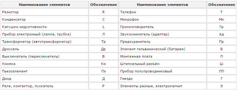
In addition, in the domestic marking of elements of radio engineering and electrical circuits, the following letter designations are distinguished:
This concludes the brief overview of symbols in electrical circuits. We hope that now you know how sockets, switches, lamps and other circuit elements are indicated on the drawings and plans of residential premises.
Also read:






Hello
the “luminaire with an incandescent lamp for special lighting” and the “pendant lamp holder” have the same reference designation. How to determine where to install? Or is there a mistake?
On the wiring diagram, the electrician outputs a wire with a margin of 20-25 cm and connects it to the corresponding switch in the junction box. So no difference
the author is not confused by the mention of GOST 1955 ??? Turn your head to the calendar-62 years is a bit much !!! It is very appropriate to indicate the dates of GOSTs. Best regards
2019, we are in college doing all the schemes for this guest. Or there over 60 years, nothing has really changed simply. The same designations, the truth of the new dofig
And what does it mean (in a group with outlets of the same size) a black square and two dashes outward (II) and a black square, a dash with three branches outward (-
tell me what is it
Very nice site. Thanks for the help, I could not have done it without you.
How to explain the scheme? Tomorrow's defense I'm not a boom boom.