Conventional graphic designation of electric motors in the diagram
In order to draw an electrical diagram, apply conventional graphic notation of all elements. So in a simplified version, you can depict any element - a resistor, capacitor, electric motor, etc. They are standardized for the main types of elements, in this article we will consider the designations of electric motors in the diagram.
Graphic designation of electrical machines
For schematic designation, a special ESKD system was developed, according to which any engine can be displayed on the drawing. It is presented in the form of a circle, next to which a letter designation can be indicated. For example, DG is the main engine, LH is the machine spindle feed motor, DO - cooling pump, etc. Let us consider which UGOs the system standardizes; a complete list is given in GOST 2.722-68
DC motors
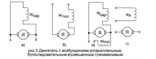
DC machines have a designation depending on the type of excitation. The figure shows direct current electric motor with various UGO options.
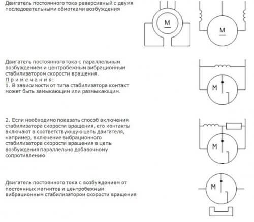
In addition, there are many devices with additional features. For example, a reversible electric motor with two windings or with parallel excitation and a vibration speed controller. The following are the UGO of such devices.
Asynchronous machines
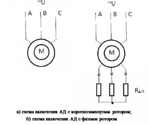
Induction motors are depicted in the drawings in the form of a circle, within which a smaller circle representing the rotor.
 The illustration shows a graphic designation of an asynchronous squirrel-cage electric machine in a single-line circuit. For a three-phase network, the symbolic representation of a phase and squirrel-cage motor is performed in a similar way, the difference is only in the number of wires and the connection of the rotor circuit.
Moreover, if the electric motor is three-phase, the connection diagram of the windings is indicated. For example, connection a star denoted as follows:
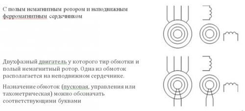
Each type of three-phase asynchronous machine has a different view in the drawing. Below are the options for graphic designation of engines of various designs.
Synchronous machines
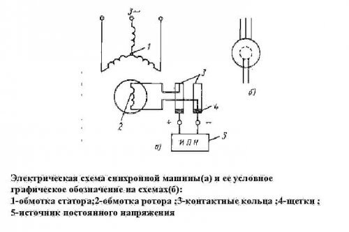
Synchronous machines according to GOST are presented in the form that is indicated in the illustration below, while the scheme is easy to read even by a lay person.
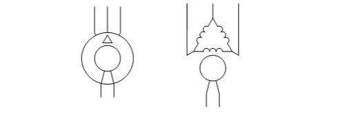
An open-pole machine with an armature winding is displayed on the diagram in the form of two circles, here both the outer and the central wires are connected (to the stator and rotor, respectively).
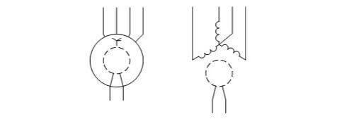 If the windings are connected by a triangle, then the synchronous motor will be depicted in the drawing in a slightly different way.
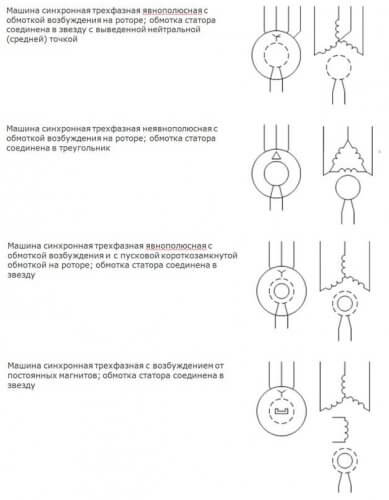
The remaining varieties of UGO types of electric motors in the diagrams are presented with a description in the figure below.
Generators
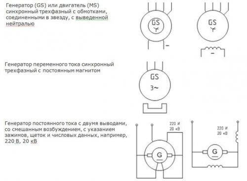
The designation of three-phase generators, like synchronous motors, has the same graphic style.Below are the images that are displayed in the diagram.
UGO of other types of electric machines
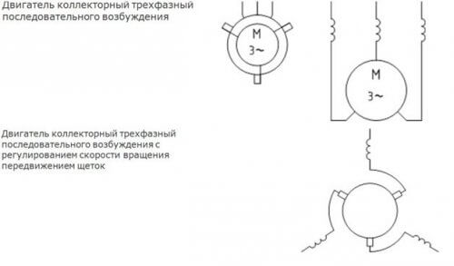
In addition to common devices, special ones are used, which also have their designation in the diagram.
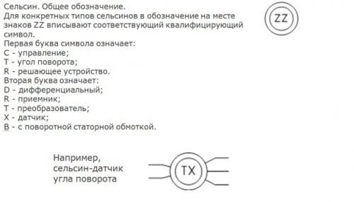
Special devices such as selsyn sensors and receivers have, in addition to the graphic designation, an alphabetic description, which is illustrated in the figure below.
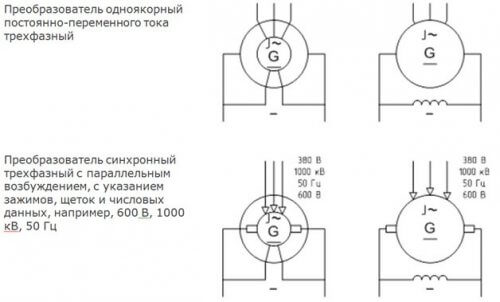
The motor-converter has an image on the diagram in accordance with the UGO. Its outline in the diagram is shown in the illustration.
Here are devices that have a collector assembly. It has an UGO in the form of two rectangles on the sides of a circle.
Conclusion
The graphic designation of electrical machines in the diagrams is performed in accordance with GOST 2.722. When drawing up the scheme, it is necessary to be guided by this documentation. It describes all the necessary machines, and also indicates the dimensions of the circle and other elements of the figure, which should be on the drawings and other requirements for the drawing.

