How to calculate the ground loop for a private house?
What is important to know
Grounding at home necessary in order to reduce the contact voltage to a non-hazardous indicator. Thanks to him, the potential is sent to the earth and protects a person from electric shock. In PUE (Chapter 1.7, Section 1.7.62.) it is indicated that a private house should have a spreading resistance with three-phase power supply of 4 and 8 Ohms (the first value at 380 V, the second - 220 V), and with a single-phase - 2 and 4 Ohms.
The number of grounding conductors must be selected in such a way as to provide regulatory resistance to the spreading of electric current. The lower the resistance - the better, thus ensuring the effectiveness of the grounding device when performing the functions of protection against the action of electric current.
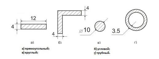
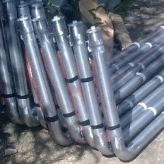
The electrodes are made of copper, galvanized and black steel. Section profiles are shown in the figure below:
Calculation Method
The calculation is based on what kind of grounding is used. The formula indicates the number of earthing switches used, their length and thickness. Also, everything depends on the parameters of the soil that surrounds the private house.
There are several options for installing grounding conductors. These are methods such as:
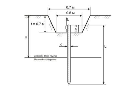
- Vertical. Divide into two subspecies: one that is installed near the surface and one that is mounted with a recess (preferably 70 cm).
- Horizontal. Divide into two subspecies: with installation on the surface of the soil and in a trench (preferably 50 - 70 cm).
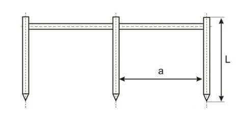
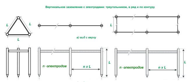
Grounding includes horizontal and vertical rods, which are calculated separately. Depending on the length of the rod, the distance between them is taken, that is, the size of a must be a multiple of the size of L. Example: a = 1xL; a = 2xL.
The formula for calculating a single vertical rod that is not buried in the soil is as follows:
Where:
- p - soil resistivity;
- l is the length of the ground electrode;
- D is the diameter of the electrode.
Note: if the ground has an angle profile with a width bthen d = 0.95b.
The calculation of the ground electrode, which is mounted with a depression of 70 cm (h = 0.7 m) into the ground, is carried out according to the following formula:
Horizontal grounding at the surface is calculated by the formula:
Note: formula provided for rectangular and pipe profile with shelf width b, for a strip to consider dneed given d= 0.5b.
The calculation of the electrode, which is located in a trench of 70 cm (h = 0.7 m), is performed according to the following formula:
For a strip of width b, d = 0.5 b must be considered.
The calculation of the total resistance of the ground electrode is carried out as follows:
Where:
- n is the number of vertical grounding conductors;
- Rв and Rг - resistance of the grounded elements;
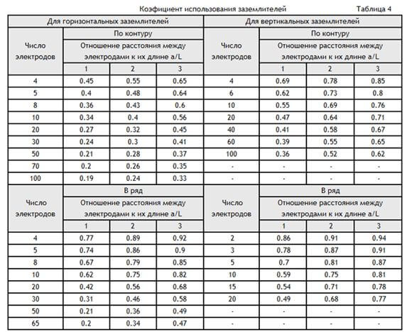
- nv is the coefficient of use of grounding conductors.
This coefficient is taken from the table:
Using the utilization coefficient method, it is possible to determine what effect the spreading currents from grounding conductors exert on each other during their various placement. For example, if they are combined in parallel, then the spreading currents of the electrodes have a mutual effect on each element. Therefore, with a minimum distance between the elements, the resistance of the grounded circuit will be much larger.
Grounding takes place according to several electrode arrangements. The most common is the scheme in the form of a triangle. But this is not a required electrode configuration. They can also be placed in one line or sequentially along the contour. This option is convenient when a small narrow area on the ground was allocated to equip the system.
Additionally you can check the result using online grounding calculator!
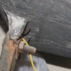
The grounding conductor connects the circuit itself to the electrical panel. Below are the diagrams:
When carrying out grounding calculations, it is important to ensure accuracy in order to prevent deterioration of electrical safety. To prevent errors in the calculations, you can use specialgrounding calculation software on the Internet, with which you can accurately and quickly calculate the desired values!
The video below demonstrates an example of settlement work in the Electric program:
Here, using this technique, grounding is calculated for a private house. We hope that the formulas, tables and diagrams provided have helped you cope with the work yourself!
Surely you will be interested in:

