Proper earthing in a private house
Importance of the issue
If you are wondering if it is necessary to make grounding in your country house or cottage, then we immediately say that you can’t do without a protective circuit. Even according to the standards of PUE, SNiP and GOST, it is necessary to make a special tap, which will protect you from electric shock. System organization TN-S (its correct name) in the 220 and 380 Volt network should be produced during construction, as then it is more expensive to do this (it will be necessary to change the two-wire cable to a three- or five-wire cable throughout the house).
If you purchased a house in which there is no grounding, then you need to mount and connect it. Installation of the grounding system is quite simple. In addition to grounding, it is necessary to create lightning protection. About, how to make a lightning rod do it yourself, we told in a separate article.
Ground loop device
Grounding and grounding requirements are defined in PUE Chapter 1.7. Also, before organizing a protective circuit, we recommend that you studyGOST R 50571.5.54-2013.
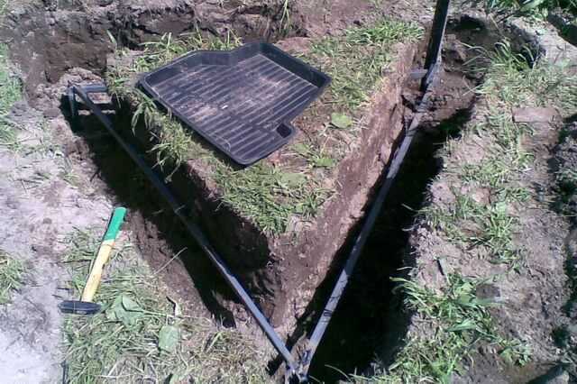
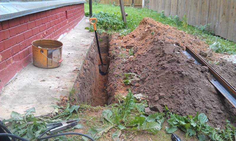
The contour of the grounding device consists of electrodes dug into the ground and interconnected by an electrode - a rod of metal or a metal strip. Usually, the ground loop is made in the shape of a triangle or square. The photo shows how to install ground electrodes in the trench.
With the grounding device, vertical grounding conductors should be laid to a depth of 0.5-0.6 m from the level of the planning level of the earth and protrude from the bottom of the trench by 0.1-0.2 m. The distance between the electrodes is 2.5-3 m. Horizontal grounding conductors and connecting strips between vertical earthing switches are laid in trenches 0.6-0.7 m deep from the level of the planning level of the earth.
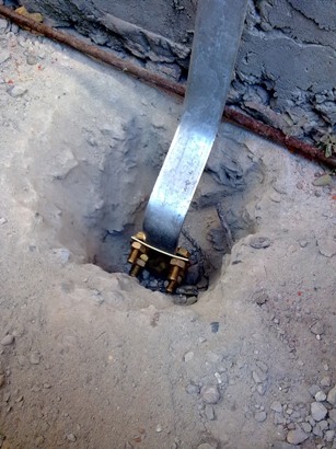
The ground loop is connected in two places with the help of grounding conductors with the internal grounding network of the house. It can be made as shown in this photo: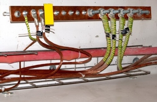
The photo shows that the ground strip is rigidly attached to the wall. Grounding strips can be attached with dowels or a construction gun directly to the wall or using intermediate parts. Stripes of sheet or strip steel up to 6 mm thick are shot with a pistol. The base should be concrete or brick.
Further we will provide you with a description of how to step by step arrange the grounding in your home.
We develop a scheme
The first step is to determine the grounding scheme in a private house, according to which you will need to make the entire system.
To date, two schemes are popular:
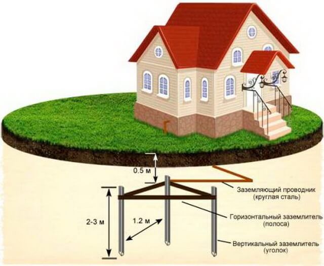
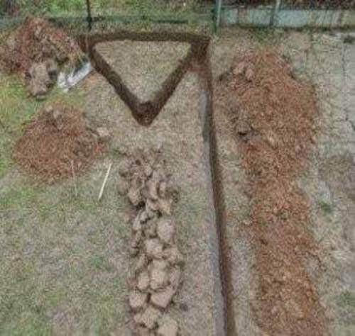
- Closed (in the form of a triangle). Its advantage is more reliable operation, as if the metal jumper between the pins is damaged, the system will still work (on the other hand). All dimensions of the triangle are shown in the picture:
- Linear In this case, all the pins are dug in one line, and the row is connected in series. The disadvantage of such a house grounding system is that if the first jumper is damaged, it will all fail (garland principle).
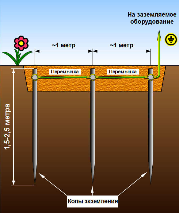
We recommend that you ground in a private house according to the triangle scheme, because in fact, the installation work will not change (you still have to dig three pits and drive three pins), but at the same time, the efficiency will be several times higher than with the in-line circuit. More about triangle grounding we told in a separate article!
In addition to the above provided grounding schemes in a private house, you can make your own version. For example, hammer the corners in a rectangle or oval. For example, we recommend that you print four of the most popular options:

Another important point is the distance between the electrodes. The figure above shows a distance of 1.2 meters between the electrodes, the length of which is 2-3 meters. This is not entirely correct. It is better to make the distance between the electrodes equal to their length, or at least 3 meters.
The thing is that with a small distance between the ground electrodes, the spreading zones of the electric current will overlap each other, which means that with current leakage, the system will not be effective. That is why it is better to separate the ground electrodes a little from each other, and most importantly - to reliably connect them with welding or special clamps.
We prepare tools and materials
As for the tools for installing grounding in a country house (for example, in the country), you will need:
- welding machine (its presence is necessary, since the connection of plates and fittings without welding will not create high-quality contact, especially under the soil);
- grinder (cut metal into suitable pieces);
- bayonet shovel;
- hammer drill;
- sledgehammer (the heavier, the better, because you have to drive the pins 2 meters deep);
- set of wrenches (tighten the bolt).
If you have at least a little electrical skills, we recommend do-it-yourself welding machine! There is nothing complicated about it!
From materials should be used:
- Stainless steel metal corner with dimensions 50 * 50 mm, at least 2 meters long. An alternative is a water pipe made of steel with a diameter of 32 mm, a wall thickness of at least 3.5 mm, or fittings. You can also use a rectangular profile, the main thing is that its cross-sectional area does not exceed 150 mm2.
- Three strips of metal 120 cm long, 4 cm wide and at least 4 mm thick.
- A metal strip of stainless steel 40 * 4 mm, having a length from the bed of the system to the porch of the house.
- Bolt M8 or M10.
- Copper wire, for example, PV-3, at least 6 mm thick2 (depending on what section is taken for the phase conductor).
Important! Do not save on the thickness of grounding conductors, as the durability and reliability of your grounding will depend on this!
Having prepared everything you need, you can proceed to the manufacture of grounding in a private house.
Installation work
Step 1 - Choosing a Location
First you need to decide in which place to make the ground loop. The importance of this stage is very high, because the safety of the use of the system depends on the choice of the grounding place in the summer cottage If there is a breakdown of the wiring, as a result of which the protection will work, then in the place where the pins are, there should not be anyone. The presence of a person or animal at the site of the removal of electricity into the soil can cause death. That is why the location of the electrodes is chosen taking into account the fact that no one will be here.It is best to place a branch along the fence behind the house, at a distance of no more than 1 meter from the foundation of the building. In addition, it is recommended to make a low fence or a border to protect an insecure area.
If you do not want to spoil the landscape design of the site, we recommend that you organize the grounding system of the apartment building under boulders or some kind of volumetric garden sculpture. In this case, no one will be able to be in the danger zone and the beauty of the infield will do nothing!
Step 2 - Earthwork
As an example, we consider how to properly make the grounding in a private house a triangle according to the scheme that we considered above. At this stage, it is necessary to dig a triangle with sides of 2-3 meters with a shovel (the most optimal distance between the corners). The depth of the trench should be from 50 to 70 cm. The same trench should be dug to the porch of the house.
Step 3 - Assembling the Design
Now the main part of the process begins. According to the scheme, it is necessary to hammer the electrodes 2 meters into the ground (so that only the tops remain, which you need to grab by welding).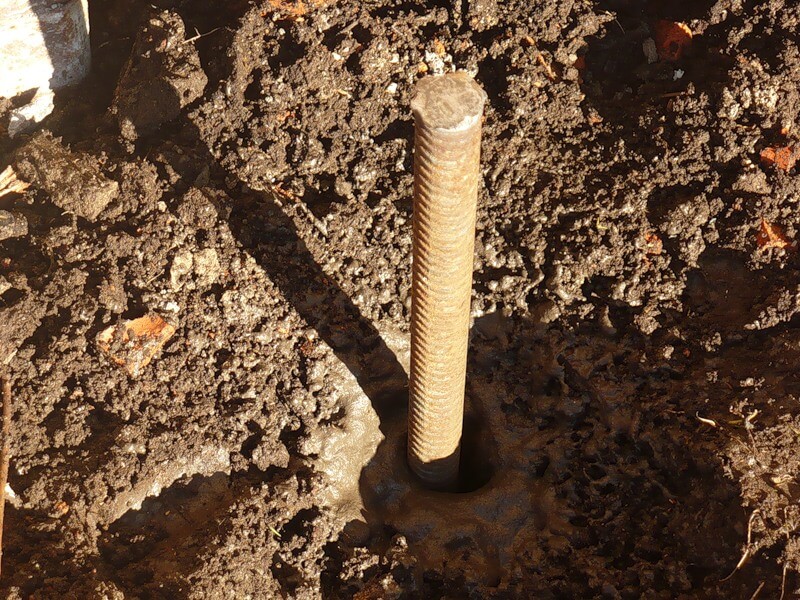
It is recommended that the grinder grind the driven end so that it penetrates the soil more easily.
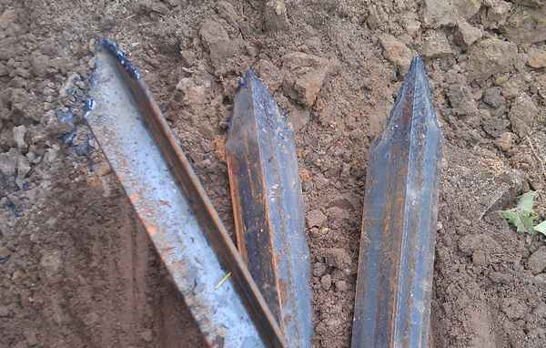
When all the pins are driven in, you need to weld the plates to the tops to get a metal triangular frame (as shown in the photo).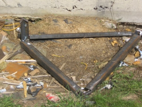
Another plate is laid in a long trench going to the house, and is grabbed at one end to the nearest peak of the triangle.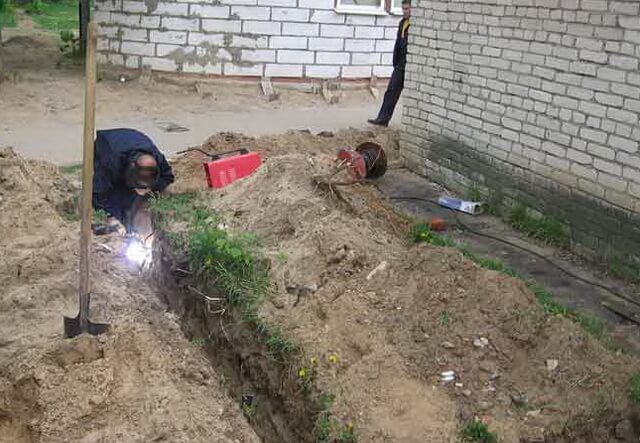
After that, you can proceed to connecting the cable to the plate using a bolt and, in the end, fill all the pits with soil back.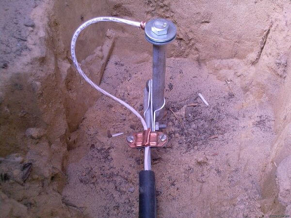
One important nuance - if the site is represented by a sand cushion, the conductivity of the soil will need to be increased with a salt solution. Liquid must be poured under the base of all electrodes. The disadvantage of such an event is that the metal begins to succumb to corrosion faster, which will make the grounding in a private house not as powerful as necessary.
Step 4 - Verification
The last thing you need to do is to measure the resistance of the finished grounding in a private house. In a good way, it is necessary to use a special electrical device for measurement, the cost of which is quite high.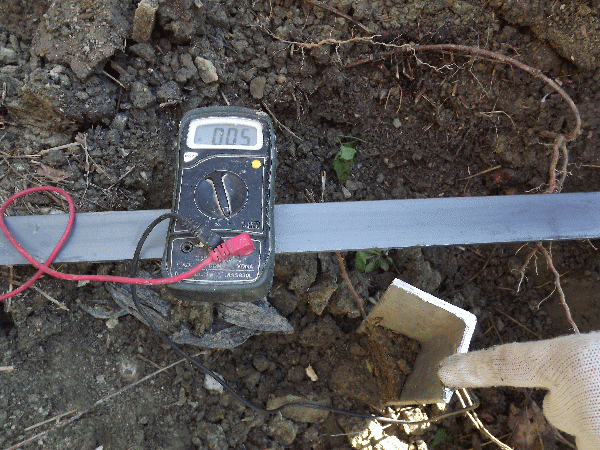
At home, you can go the other way to solve the problem, it’s simpler to check the performance using a lamp with a power of at least 100 watts. All that is needed is to connect the light source with one contact to the ground loop and the other to the phase. If the bulb burns brightly - the earthing installation in your own house was done correctly, dimly - the contact between the structural elements is weak and it is necessary to redo the joints. If the light did not appear at all, you made a mistake somewhere and you will need to completely revise the entire system, perhaps starting with the circuit itself! More about ground loop resistance measurement We talked in a separate article.
This instruction ends. We hope that now you know how to make grounding in a private house with your own hands! We draw your attention to the fact that this technology and all sizes are suitable for summer cottages too.
You can see the whole process in more detail on visual video examples:
Related materials:




Very good stuff. Everywhere I read that grounding should be done with a triangle and the question always arose - why not linear? Now I see that it can be so. Thank.
I did not understand why connect the fence.
Vladimir
Hello! We try) And where did you read about connecting the fence?
Fence is a good idea.The more ground contact the better. Ideally, the voltage measured between the ground and the neutral wire should be zero. But this never happens, usually it is and the higher, the worse the grounding.
they muddied it and connected it to the fence, read the rules how the ground should look, but didn’t connect the phase from the neighbors?
This video is not our personal one and is exemplified only so that you can see how to properly clog electrodes, isolate welding joints, etc. In the article we do not mention the connection of grounding to the fence. The masters in the video tutorial really made a mistake.
Hello! 1.Can you separate the grounding with a separate wire and what? 2. Do you need to ground the lights? thank!
Good day! As for the fixtures ... you need to ground them if the cases are metal and there is the possibility to connect a PE wire. A separate wire can not be installed to ground the house! Be sure to lay either a five-wire or a three-wire wire!
Admin, why not? Explain? What are the obstacles to this?
The protective earth conductor must be in EVERY cable. This is necessary in case of cable damage. If any cable is damaged, a leakage current should occur and an RCD will trip. If you separate the PE wire separately, you will not have protection against damage to the wiring. This is the meaning of the requirement - to breed everything with a three-wire cable (L, N, PE in each cable). Also, if you pay attention - in a PE flat cable the conductor is always in the center - between L and N conductors. This is also done for the same purpose.
Hello, tell me, a two-wire wire is everywhere in my house, but I want to ground the washer and dishwasher with a separate wire right before grounding in the ground past the shield. Tell me, do I need to pull the wire from each device to ground in the ground, or can I connect these two devices into one ground wire and drag it to the ground with one wire?
It is forbidden to ground household appliances with a separate wire. You need to change the wiring to a three-wire and make normal grounding in a private house!
“Grounding household appliances with a separate wire is prohibited. »What does this threaten?
This is threatened by the fact that most often people do grounding, implying this is a separate ground. In addition, how do you imagine a ground wire passing through a room separately, for example, if a two-wire wiring is hidden under the plaster? There will be confusion that could lead to an accident. When zero, phase and earth are in one place, or rather represented by one three-wire cable, there are much fewer problems.
Hello! In my case, it is simply impossible to change the wiring in the house. (it’s easier to build a new house with new wiring). In a free-standing bath, I arrange a shower with a pump station and a boiler (both require grounding), but only Zero and Phase (220V) are suitable for the bath. Question - can I make grounding only for the bath and how? The neighbor has no grounding and souls works on the same principle and doesn’t hit anyone with electric current? ...
Hello! You can of course make a separate ground loop according to the technology described in the article.
You are not right, the ground loop should be only one on the object, in no case do several loops on one object due to the appearance of voltage between these loops. checked, the electronics burns out for no reason, pull the bus (steel strip) to where you want from the main circuit. learn from the mistakes of others.
Good afternoon!
Useful stuff!
I have a house on screw piles. There will be a garage attached to the house. I want to concrete the floor of the garage on a sand cushion.
I have 2 questions:
1.Is it possible to place the grounding triangle under the concrete floor of the garage on the ground?
Will it be dangerous for people in case of an accident?
2. Or maybe use piles as pins, scalding them with a strip? Then no one will go there for sure.
Hello Michael! I do not recommend doing grounding under the garage: it will be difficult to do an audit, because if the circuit is damaged, you will have to break the screed. But as for piles, this is the preferred option. Although many electricians argue about this, they say the piles will rust faster with the passage of current, and the anticorrosive composition negatively affects the effectiveness of the grounding circuit. Nevertheless, grounding by piles is often used and no significant complaints about this method of protection are observed. The main thing is that the piles be dug below the level of freezing of the soil.
Hello! An input metal shield is located on the reinforced concrete support of the power transmission line. It has metering devices and machines. Three buildings were recorded from it through a cable in the ground: a house, a bathhouse, a garage. How to properly ground them? Make one contour near the support and connect with a three-wire cable, or connect with a two-wire cable and make each circuit and each metal shield. Prostation from a water board to distribution boards 7, 10, 25 meters. Thank!
Good afternoon! As practice shows, one high-quality ground loop is sufficient, provided that the distance does not exceed 10 meters and at the same time a three-wire power supply circuit is provided. According to the rules, a contour is required near each building.
Thank you for your prompt response. Now another question arose: which grounding system should the TT or TN-C-S choose. Aerial line, bare wire, N re-grounded through the armature on each support (surprised). The ground loop for each building will have its own, near the support, on which the input shield will also hang its own loop.
P.S. There will be UZO 300mA and 10mA, as well as a voltage relay.
In general, in this case, it is recommended to make a grounding system TT, but I can not recommend something without a clear overview of the whole situation. I recommend that you consult with a local electrician who knows all the features of your network.
All the salt is that local "electricians" can put Chinese amperes at 25 (with a margin) on the old Soviet wiring of 2.5mm aluminum, and unipolar on L and N. Therefore, they burn periodically at home in winter. Altai Republic.
Tin. I’m sorry that you have such “specialists”. Although there are enough of them everywhere.
Hello! I have a private house. I want to make grounding in the kitchen and bathroom (a lot of steam, etc.). The wiring for sockets is three-core, the yellow color of the core, as I understand it, is it just going to ground? While I use it without land, but if I stood with my bare feet on the tile and opened the tap with hot water, I nibble my hands very noticeably! I have such a scheme that each room has its own connecting box in the attic. Washing (entering) to the bathroom comes from the kitchen (combined blue (zero) with blue, brown (phase) with brown and yellow (earth is obtained) with yellow. But the entrance to the kitchen is two-core, completely yellow, the “input” is insulated and “empty”. Question: will the grounding work for these two rooms, if I connect the “external” circuit to the box from the kitchen? And do I still need to buy some additional devices (I plan to install an RCD), or can I just connect a wire box with a large cross section to the box and the welded fittings to the electrodes?
Hello, in principle, everything is ready for you to connect the circuit to the home system, judging by the data provided. The organization of the circuit should be taken responsibly, because correctly done, it will serve you for many years and will properly perform its function. Installing an RCD is the right thing.But you need to find out before that which of the electrical appliances is leaking. A leak on the case is not the normal mode of operation of electrical appliances, the RCD will not allow it to be turned on. And grounding will not solve the problem completely. Check out the article on our resource https://our.electricianexp.com/en/pochemu-stiralnaya-mashinka-betsya-tokom-i-kak-eto-ispravit.html and identify the culprit of the leak.
Thanks for the advice! And a couple of questions: on some site I read that each device (in my case, each of 4 outlets) needs to be grounded separately on the ground strip, that is, a wire from the external circuit and 4 terminals from outlets should go to it. The questions are as follows: why it is impossible to ground with a serial connection (as I wrote in the first post), and how can I then bring the "ground" from the sockets to the bar (to ground in a box or what?) ?! By the way, I’m almost sure that the electric boiler “breaks through”, because if it is turned off from the outlet, then the water does not “pinch”, and even when turned on it does not hit if the mixer is in the extreme position (only cold water flows). It turns out to hit ten?
If the sockets are separated through the installation box and all the connections are made in it, insert a protective conductor into it, make the connection (you need to throw the wire from the circuit from the circuit to the box). If the ten began to punch, it is worth replacing it, since its service life is rapidly coming to an end. The shell is destroyed and the water contacts the heating element. The test procedure for the heating elements we described in the article https://our.electricianexp.com/en/metodika-proverki-rabotosposobnosti-tena.html
And if you will make land for all rooms, then in the attic you should make a separate box with a terminal and enter earth wires from the boxes there. Please note that daisy chaining grounding wires is prohibited. They must be kept separately from each box to this terminal, as required by the rules of the PUE.
And what does a garland mean? I don’t know about “all rooms”, since only a couple of years ago I changed the wiring and did not provide grounding, but only to the bathroom and kitchen (they are the most dangerous). But it is interesting that the boiler was only 11 months in operation, and began to break even half a year ago, immediately barely, and then more noticeably. Another joke is that I didn’t pinch in the bathroom (acrylic bathtub), but only from the washstand and when barefoot on the tile ... Why is that?
It is intended not to connect the ground wires from the box to the box in series. Each wire should go separately.
Driving a PE wire from each of the outlets in the group separately to the grounding point is a series of bad tips. Each group of outlets must have its own three-wire cable, with protective grounding inside this cable. And nothing more. It is not necessary to lay any separate grounding wires to each of the outlets in the group. To comply with the PUE “in each letter” - in the first of the socket boxes in the group, a sleeve (GML) is placed “under pressure” for the required number of PE conductor taps to each of the outlets in this group. In practice, all sockets (including the most super-duper-branded) are made for the possibility of connecting, including the PE conductor "loop" - sequentially from socket to socket. And it is better to reliably connect PE with a “cable” for the screw (in the socket itself) - this is exactly what they do in 90% of cases than to invent your own “bicycle” - especially if the installer does not have a press. Who doubts the correctness of this decision - unscrew any extension cord and make sure that no extension cord has a bunch of separate PE wires from the plug to each of the outlets in the extension cord. 🙂
And can ground wires from sockets on the second floor be twisted together, and then brought to the bus?
There is a house with a foundation stove, there are a lot of fittings in the stove. Is it possible to connect grounding to the reinforcement in the foundation?
Thank!
No, of course, grounding should be a single device, and reinforcement in concrete does not meet these criteria, that is, today there is contact and six months later it will oxidize and the contact between the reinforcement will become high-resistance or cease to be. Another thing, if the armature is grounded, is between the case. And use as a grounding device or grounding element is strictly prohibited.
Hello.Is it possible to place a triangle contour under the living room? The floor level in this place will be raised above ground level with the min contour of 50-60 cm located in it. There is no structure yet and nothing prevents the device from installing the contour, except for doubts about the safety of its future use.
Hello! This option is bad because you will not be able to check the circuit in the future and repair it if the contact is broken.
Thanks for the answer, the lack of the ability to service or repair the circuit is not scary. Yes, and there is simply no other place for an earthing device at the moment, so the question of 100% safety for people above it is of interest.
In this regard, you can not worry. If the installation is carried out correctly, the circuit does not pose a hazard even under the living room.
Is it possible to connect it in some other way if there is no welding available ??
Hello! Everywhere it is indicated that the corners should be hammered, but I have rocky soil. Is it possible or not to drill holes with a hole-hole drill and insert corners there, what kind of soil would be best to fill these holes later? As I understand it, the more pins the better?
Thanks in advance for your reply.
There are two ways to lay grounding conductors. It is vertical and horizontal. With a vertical type, the electrodes are clogged down, with a horizontal type, they lie in a trench. The horizontal type of grounding is just performed in rocky soils.
Hello! We are doing major repairs and changing the general input of electricity. They began to do grounding, but it seems to me that it is not at all right. I read your article and realized that this is a linear grounding system. They are laying it for us in the flowerbed in the center of the yard, not deeply. And a metal strip is laid over the path along which the tenants of the house walk and will be screwed directly to the wall near the front door.
Attaching photo.
Maybe I'm worried in vain? But I'm afraid that such a ground can kill someone.
Good day! I don’t see the photo where you put it. You’re not in vain, it’s better not to mess with such masters. As for the danger, it all depends on what kind of soil and what resistance was measured by a megaometer when the corners were driven into the ground, and to which these tires were welded. Tires should not go over the track, they are dug into the ground!
Hello! What if you build an earth loop in the basement wall, 1.5 meters below ground level? Those. to drill a wall and hammer pins? The floor is concreted. I want to bring the grounding to the washing machine and electric heater, which are in the basement.
The ground loop must comply with safety regulations and the required resistance. It is better when it is soil and angles or pins are driven into it to a certain depth depending on the soil. The wall or floor must match the resistance, which is checked by a megaometer.
Good afternoon, I read from you that there should never be anyone in the grounding zone!
And further, what circuit can be arranged under the living room ??! Is there a contradiction here?
The fact is that I would like to make a contour in the gazebo (there is no place around) But will there always be people there ???
Good afternoon! great article! tried and gathered everything in one material
Tell me, how much is it reasonable to use galvanized metal for grounding?
More expensive but kind of "forever"
Thank! There is no special difference. The main thing is that the circuit resistance corresponds to the standards.
The main thing is that it complies with GOST R 50571.5.54-2013 / IEC 60364-5-54: 2013 (Table 54.1) and the applicable regulatory documents. So there is still a difference.
Hello. Made a sewer: septic tank and filter well. The well has not yet been sprinkled with rubble. Question. Is it possible to make grounding to the filtering well, or around it. Humidity (contact with the ground) will always be good there. But how is it from the point of view of safety during the breakdown. Will all the plumbing become dangerous?
It is better to make a separate circuit next to the sewer. It will be both correct and safe.
Why is stainless steel in the article, but in all the photos we use black metal?
Photos for example provided, taken from the network. Stainless steel is better for grounding, but ferrous metal is cheaper, so it is used more often.
My comments. The distance between the electrodes in the ground is 2.5-3m. If the steel is round, then the length is 5m. According to the draft art. strips 40 * 4mm, Energy surveillance requires a thickness of 5mm or more. Bolted joints underground are not allowed, only welded joints coated with bitumen varnish. The resistance of the ground loop is 30 Ohms or less, if your line is the only one on this line, then the resistance is 10 Ohms or less. p.1.7.103.
A grounding copper wire of at least 10 square mm must not be immersed in the ground, Art. the strip should go to a height of 2.5 m from ground level, then the copper wire is connected by a bolted connection, preferably a nickel-chrome coating.
In his house, he used a stainless strip 5 mm thick and 30 mm wide as a GZSH.
Hello! Already on which forum I’m trying to find out, but I’m not getting clear answers anywhere. Will I try here?
According to the technical specifications for receiving 380v 3F + PEN in a private house, I have to install a pole on the border of the site, mount a shield on it with a metering device, grounding for this shield + automatic machine 32A in this switchboard. Questions:
1. Is it necessary to re-ground the conductor coming from TP PEN in this shield or simply ground the shield from the ground loop?
2. What kind of automatic machine to use (3-pole, 4-pole or some other)?
3. From this shield to the main switchboard in the house about 25 meters. Accordingly, for the house, I planned to carry out a separate ground loop. And perform the separation of PEN into PE and N already in the main switchboard. Accordingly, after separation already put the circuit breaker and then assemble the circuit. Is it possible to do this (taking into account the fact that the circuit breaker will already have a circuit breaker on the pole and the PEN in the shield is re-grounded but not separated)?
1. Re-grounding the PEN conductor is done by the supplying organization. Re-grounding is performed primarily along the entire line at certain intervals, the number of re-grounding is determined during the design of the line. For grounding reliability, the PEN is also grounded before separation in the shield. But this should be done by the supplying organization and only on condition that the line from the transformer substation is in a normal technical condition and, as expected, repeated grounding of the PEN conductor is made. If this is not so, then you can not ground the shield to your circuit, because in the event of a zero break somewhere on the line along your ground loop through the PEN conductor from the line, a load current will flow, which flowed through zero for the entire street (depending on where zero broke).
2. Place a three-pole circuit breaker in the metering board, since the PEN conductor cannot be broken to the separation point.
3. For re-grounding, read paragraph 1.
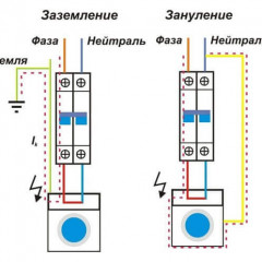
The use of an individual grounding loop in a house is a TT grounding system. With this system, the grounding of the wiring is connected to the grounding loop, and the PEN conductor of the line is used only as the neutral wire N.
Good afternoon.
here I am: I have intricate initial conditions.
The power input circuit resulted in a file.
In words: grounding, as I understand it, according to the CT scheme, 3 phases, but earth and neutral enter the house through one wire.
I would like to INSTALL a common RCD (as I understand it, to 4 terminals) and RCD by groups (for example, water supply equipment).
Can you advise something?
I do not see the file.
apparently something with the site: everything correctly attached.
I try again, or tell me which address you can throw a picture
If I need to ground only one equipment and a power supply socket for this equipment, will it not work? An old-style house, two-core food comes there.
Good afternoon! I have a private house, brick. No grounding. I plan to do. Is it possible to mount the grounding (plug pins into the ground) next to the concrete pillar of the overhead power line, from which my house and the houses of my neighbors are powered? The zero line on this pole is already grounded. After all, if somewhere in my house there will be a phase breakdown to the ground, then under the ground this current can get to the wire rod, grounding the zero line and then to the zero line itself ... I’ll also add, in my house, in front of each group of machines there is an RCD or differential. automatic machines.
Hello! Tell me, is it possible to make a triangle outside the area in front of the red line, behind the fence? And what distance should be from the foundation of the fence to the triangle?
What kind of nonsense? Why should a stainless steel angle be used? Where did you find this information?
Good afternoon! On an extended stretch there is a bathhouse and a garage with a living room, the distance between which is about 70 meters. 1) Do you need to do two separate ground loops? 2) Is it possible to make one of the contours in the basement under the garage (now I am just concreting the floor and walls in the basement). The height of the basement is 1.8 m, that is, you don’t have to dig and score much, BUT the question is safety when in the cellar ?! Thanks in advance!
Why is the ground loop necessary to do at a distance of 1 meter from the foundation? And if less? And also about the depth of the contour, it is not clear.
When installing the grounding triangular circuit, bring the grounding to a height of about half a meter from the ground, and then 6 meters to conduct a copper wire to the electricity metering panel of 380? or do you need to lead the ground loop with an iron or stainless strip 40 * 4?
Is it possible to apply reinforcement for building earthing rods f16
No, in no case can the reinforcement be used because it rusts very much and when the reinforcement is clogged, its uneven surface will fluff up the ground, as a result of which contact with the ground will be worse
Hello, please tell me what needs to be done for: after thunder and lightning, the main fuse always blows out, is the reason for poor grounding? And what needs to be done for this? Regards E Zastava
Hello. I would like to know whether it is possible to make a ground loop by using pipes (5-6 pcs.) With a diameter of 40 mm, a length of 2.5-2.8 m, a wall thickness of 3 mm as vertical electrodes. Thanks in advance.