How to get a voltage of 12 volts
We get 12 volts from 220
The most common task is to get 12 volts from a 220V household power supply. There are several ways to do this:
- Reduce voltage without transformer.
- Use a 50 Hz mains transformer.
- Use a switching power supply, possibly paired with a pulse or linear converter.
Undervoltage without transformer
There are 3 ways to convert voltage from 220 Volt to 12 without a transformer:
- Reduce voltage with a ballast capacitor. A universal method is used to power low-power electronics, such as LED lamps, and to charge small batteries, as in flashlights. The disadvantage is the low cosine of the Phi circuit and the low reliability, but this does not prevent it from being used everywhere in cheap electrical appliances.
- Reduce voltage (limit current) with a resistor. The method is not very good, but it has the right to exist, suitable to power some very low load, such as an LED. Its main drawback is the release of a large amount of active power in the form of heat on the resistor.
- Use an autotransformer or choke with similar winding logic.
Quenching capacitor
Before you begin to consider this scheme, you should first say about the conditions that you must comply with:
- The power supply is not universal, so it is calculated and used only for working with one known device.
- All external elements of the power supply, for example, regulators, if you will use additional components for the circuit, must be insulated, and plastic caps are put on the metal handles of the potentiometers. Do not touch the power supply board and wires to connect the output voltage if the load is not connected to them or if the zener diode or stabilizer for low DC voltage is not installed in the circuit.
Nevertheless, such a scheme is unlikely to kill you, but you can get an electric shock.
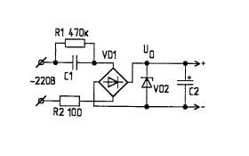
The diagram is shown in the figure below:
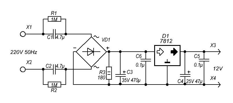
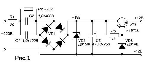
R1 - needed to discharge a quenching capacitor, C1 - the main element, a quenching capacitor, R2 - limits the currents when the circuit is turned on, VD1 - a diode bridge, VD2 - a zener diode for the desired voltage, for 12 volts suitable: D814D, KS207V, 1N4742A. You can use a linear converter.
Or an enhanced version of the first scheme:
The value of the quenching capacitor is calculated by the formula:
C (μF) = 3200 * I (load) / √ (Uinput²-Uoutput²)
Or:
C (μF) = 3200 * I (load) / √Uinput
But you can use the calculators, they are online or as a program for the PC, for example, as an option from Goncharuk Vadim, you can search the Internet.
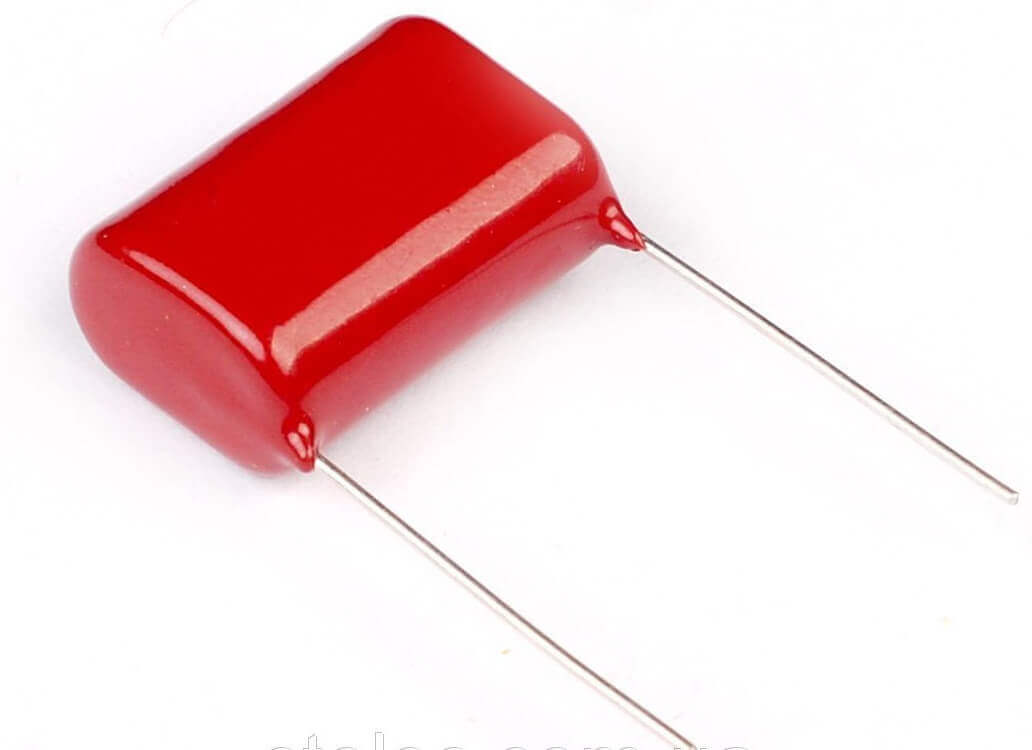
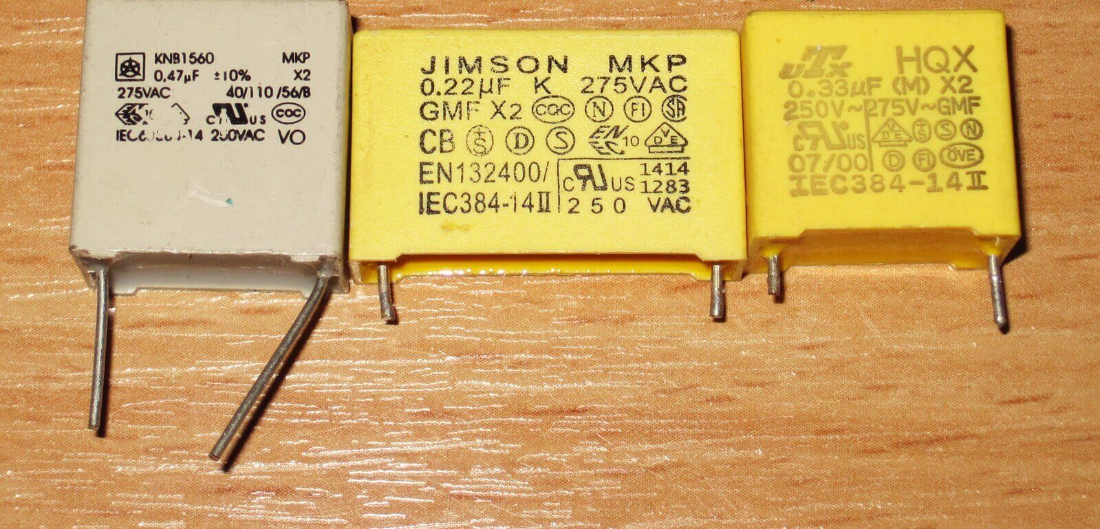
Capacitors should be like this - film:
Or such:
The rest of the listed methods does not make sense, because lowering the voltage from 220 to 12 Volts with a resistor is not effective due to the large heat generation (the dimensions and power of the resistor will be appropriate), and it is impractical to wind a choke with a tap from a certain turn due to labor costs and dimensions.
Power supply on a network transformer
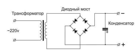
A classic and reliable circuit, ideal for powering sound amplifiers such as speakers and radio tape recorders. Provided that a normal filtering capacitor is installed, which will provide the required level of ripple.
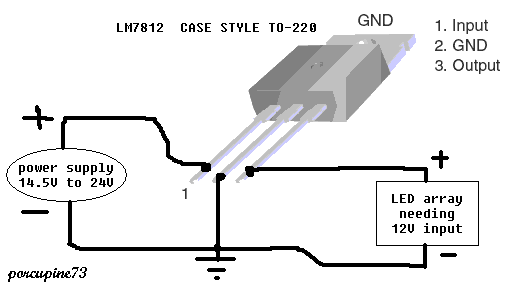
In addition, you can install a 12 volt stabilizer, such as KREN or L7812 or any other for the desired voltage. Without it, the output voltage will change according to voltage surges in the network and will be equal to:
Uout = Uin * Ctr
Ktr is the transformation coefficient.
It is worth noting here that the output voltage after the diode bridge should be 2-3 volts more than the output voltage of the BP - 12V, but not more than 30V, it is limited by the technical characteristics of the stabilizer, and the efficiency depends on the voltage difference between the input and output.
The transformer should give out 12-15V of alternating current. It is worth noting that the rectified and smoothed voltage will be 1.41 times the input voltage. It will be close to the amplitude value of the input sine wave.
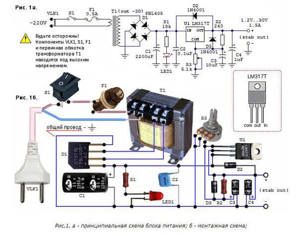
I also want to add an adjustable PSU circuit to the LM317. With it, you can get any voltage from 1.1 V to the value of the rectified voltage from the transformer.
12 volts out of 24 volts or other high DC voltage
To reduce the DC voltage from 24 volts to 12 volts, you can use a linear or switching stabilizer. Such a need may arise if you need to supply 12 V to the load from the on-board network of a bus or truck with a voltage of 24 V. In addition, you will receive a stabilized voltage in the car's network, which often changes. Even in cars and motorcycles with an on-board network of 12 V, it reaches 14.7 V with the engine running. Therefore, this circuit can also be used to power LED strips and LEDs on vehicles.
The linear stabilizer circuit was mentioned in the previous paragraph.
You can connect a load of up to 1-1.5A to it. To amplify the current, you can use a pass-through transistor, but the output voltage may decrease slightly - by 0.5V.
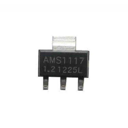
Similarly, you can use LDO-stabilizers, these are the same linear voltage stabilizers, but with a low voltage drop, such as AMS-1117-12v.
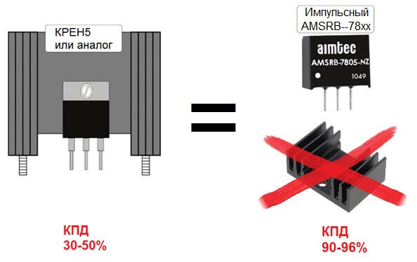
Or pulse analogues like AMSR-7812Z, AMSR1-7812-NZ.
Wiring diagrams are similar to L7812 and Banks. Also, these options are suitable for lowering the voltage from the laptop power supply.
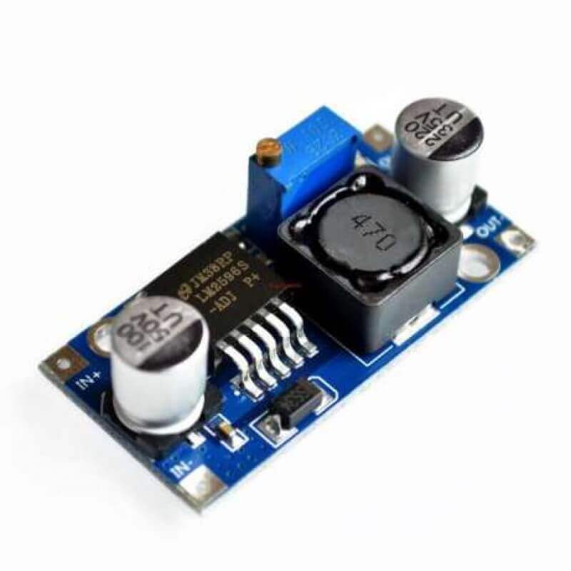
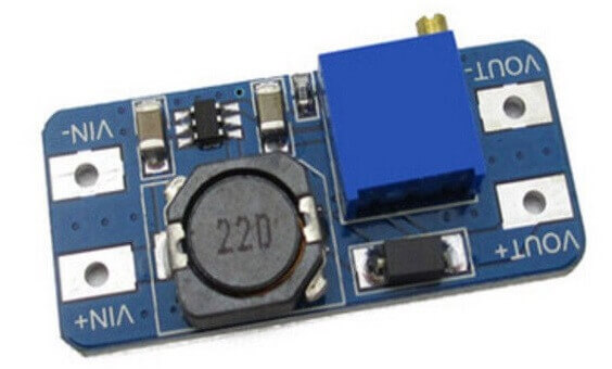
It is more efficient to use pulsed step-down voltage converters, for example, based on the LM2596 IC. The pads are signed on the board In (input +) and (- Out output), respectively. On sale you can find a version with a fixed output voltage and with an adjustable one, as in the photo on the top right you see a multi-turn potentiometer in blue.
12 volts out of 5 volts or other undervoltage
You can get 12V from 5V, for example, from a USB port or a charger for a mobile phone, you can also use it with the now popular lithium batteries with a voltage of 3.7-4.2V.
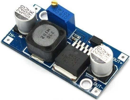
If we are talking about power supplies, you can intervene in the internal circuit, edit the source of the reference voltage, but for this you need to have some knowledge in electronics. But you can make it easier and get 12V with a boost converter, for example, based on the XL6009 IC.On sale there are options with a fixed output of 12V or adjustable with adjustment in the range from 3.2 to 30V. The output current is 3A.
It is sold on a finished board, and there are notes on it with pin assignments - input and output. Another option is to use MT3608 LM2977, increases to 24V and can withstand the output current up to 2A. Also on the photo are clearly visible signatures to the contact pads.
How to get 12V from improvised means
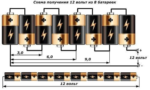
The easiest way to get 12V voltage is to connect 8 1.5V finger batteries in series.
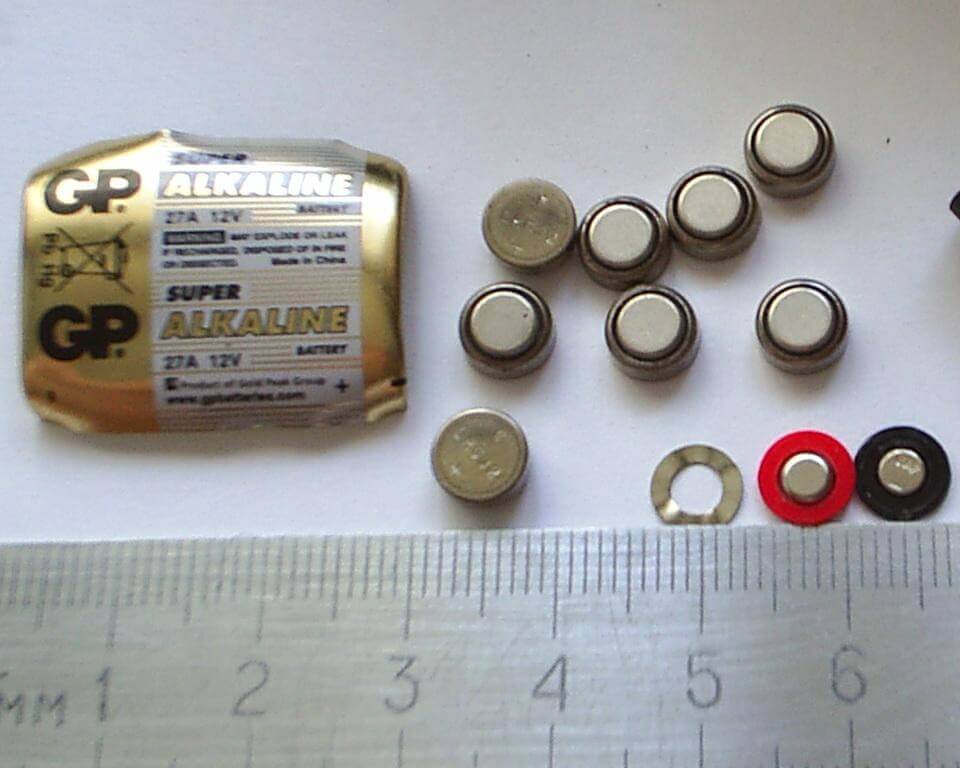
Or use a ready-made 12V battery marked 23AE or 27A, such are used in remote controls. Inside it is a selection of small “pills” that you see in the photo.
We considered a set of options for getting 12V at home. Each of them has its pros and cons, a varying degree of efficiency, reliability and efficiency. Which option is better to use, you should choose yourself based on the capabilities and needs.
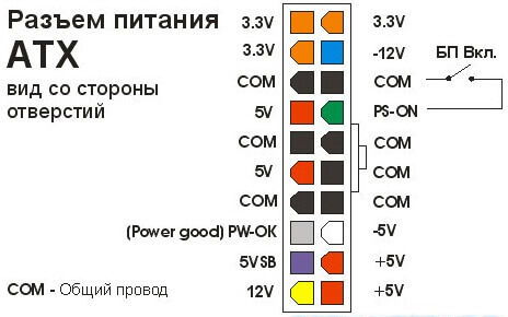
It is also worth noting that we did not consider one of the options. You can get 12 volts from the power supply for an ATX-format computer. To run it without a PC, you need to short the green wire to any of the black ones. 12 volts are on the yellow wire. Typically, the power of a 12V line is several hundred watts and a current of tens of amperes.
Now you know how to get 12 volts from 220 or other available values. Finally, we recommend watching a useful video on the topic:
Surely you do not know:




I was interested in the regulated PSU circuit on the LM317. IMPORTANT QUESTION and which transformer is here on the circuit, and do you have this circuit inSprint-Layout or in a similar program.
Yes, too, drew attention to the strange UGO of this trance
What strange thing did you see in the UGO transformer, but you didn’t notice that there electrolytes were not drawn according to Russian state standards, and diodes too. It says that the secondary in a trance should give out 30 volts for a change. For the LM317, up to 40 volts can be input. Accordingly, the difference between the input and output voltage should be no more than 40 volts.
In this case, the voltage at the input of the microcircuit should be at least 2 volts more than at the output. Those. on the regulator (stabilizer) LM317 a couple of volts is lost. Accordingly, power equal to the voltage difference between the input and output multiplied by the current through the microcircuit is allocated. Therefore, the greater the difference between input and output, the lower the efficiency.
I’m all for what, to the fact that you can use any transformer that satisfies the described conditions! Why is the circuit in a spring light, if there is a wiring - 2 tires and up to 10 holes .. Assembled on a breadboard or mounted installation. Or do you want an electric circuit diagram in a classic form?
Why is there a 35V capacitor C3 on the second circuit after the bridge? Isn't that 220 there? Also, the meaning of the capacitor C2 is not disclosed.