How resistors are labeled in terms of power and resistance - overview of standards
Denomination in letters and numbers
On Soviet-made resistances, alphanumeric marking of resistors and the designation with color bars (rings) are used. An example can be considered resistors of the MLT type, on them the resistance value is indicated in the alphanumeric way. Resistors up to hundreds of ohms contain the letter “R”, or “E”, or “Ω” in their markings. Thousands of ohms are marked with the letter “K”, millions are marked with the letter M, i.e. the letters determine the order of magnitude. In this case, whole units from fractional are separated by the same letters. Let's look at a few examples.
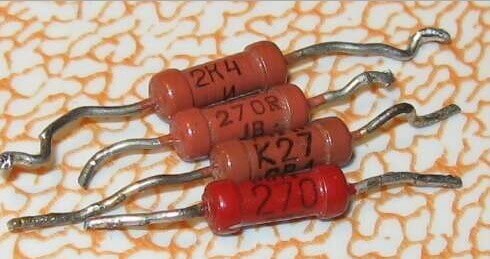
In the photo from top to bottom:
- 2K4 = 2.4 kOhm or 2400 Ohm;
- 270R = 270 ohms;
- K27 = 0.27 kOhm or 270 Ohm.
The marking of the third is incomprehensible, perhaps it is deployed on the wrong side. In addition, power resistors may be present on resistors from 1 W. Marking is quite convenient and visual. It may vary slightly depending on the type of resistors and the year of manufacture. There may also be an extra letter that indicates the accuracy class.
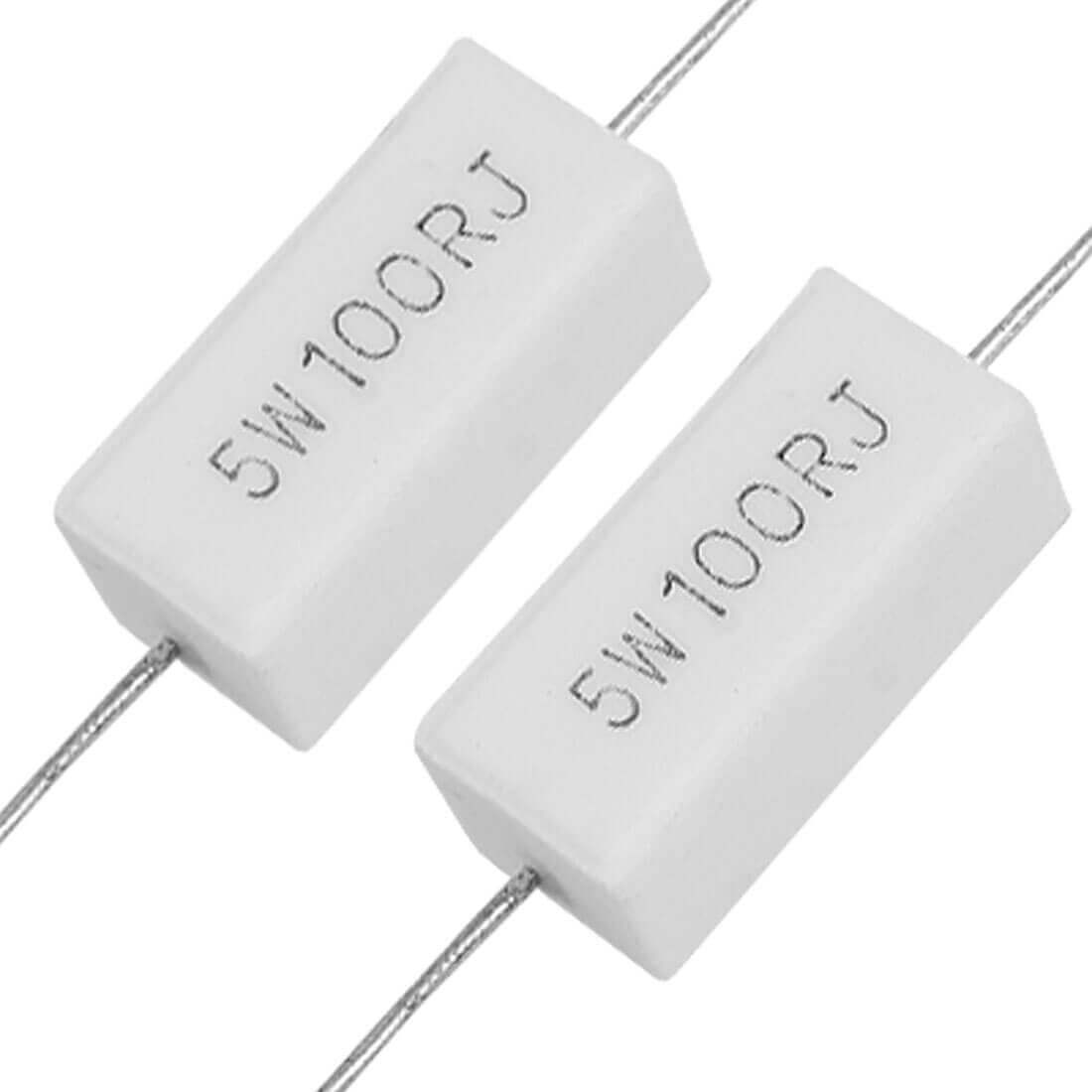
Imported resistance, including Chinese, can also be marked with letters. A striking example is ceramic resistors.
In the first part of the designation, 5W is indicated - this is a resistor power of 5 watts. 100R - means that its resistance is 100 ohms. The letter J indicates a tolerance of deviations from the nominal value of 5% in both directions. The full tolerance table is shown below. The accuracy class or the permissible deviation from the nominal value does not always significantly affect the operation of the circuit, although this depends on their purpose.
How to determine the value of the color rings
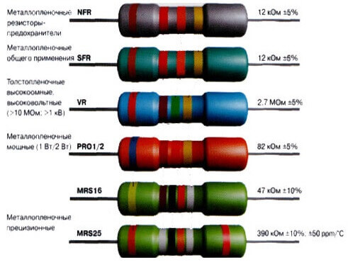
Recently, output resistances are often indicated using color bars and this applies to both domestic and foreign elements. Depending on the number of color bars, the way they are decoded changes. In general, it is assembled in GOST 175-72.
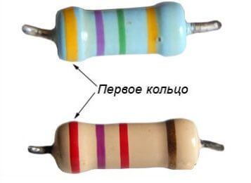
The color coding of resistors may look like 3, 4, 5, and 6 color rings. In this case, the rings can be shifted to one of the conclusions. Then the ring, which is closest to the wire output, is considered the first and the decoding of the color code begins with it. Or one of the rings may be absent, usually the last but one.Then the first is the one near which there is a couple.
Another option is when the marking rings are evenly spaced, i.e. fill the surface evenly. Then the first ring is determined by color. Suppose one of the outermost rings (the first) cannot be golden, then you can determine which side the report is on.
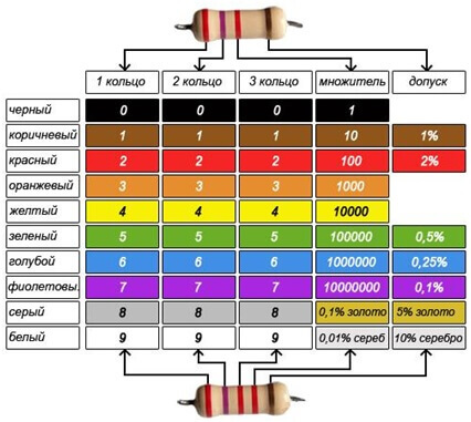
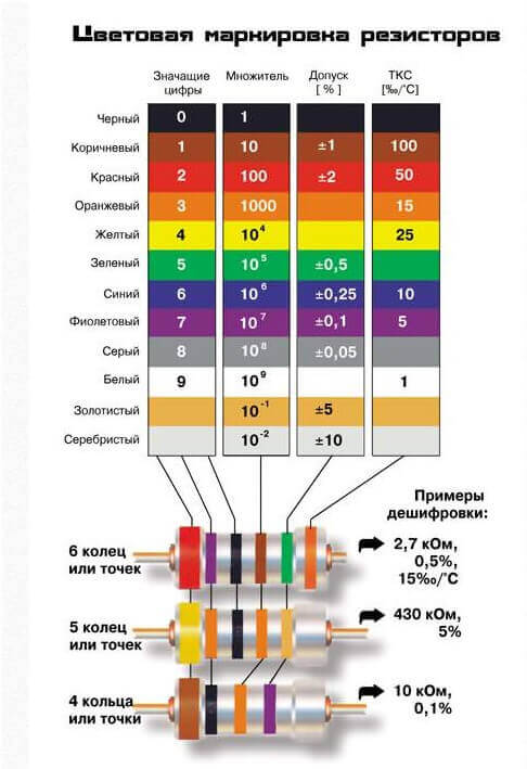
Note with this method of marking of 4 rings, the third ring is a multiplier. How to understand this table? Take the upper resistor, the first ring of red is 2, the second of violet is 7, the third, the factor of red is 100, and our brown tolerance is 1%. Then: 27 * 100 = 2700 Ohm or 2.7 kOhm with a tolerance of 1% deviation in both directions.
The second resistor is color-coded from 5 bands. We have: 2, 7, 2, 100, 1%, then: 272 * 100 = 27200 Ohms or 27.2 kOhms with a tolerance of 1%.
For resistors from 3 bands, color marking is performed according to the following logic:
- 1 strip - units;
- 2 strip - hundreds;
- 3 band - multiplier.
The accuracy of such components is 20%.
The ElectroDroid program will help you decrypt the color designation, it is available for Android in the Play Market, its free version has this feature.
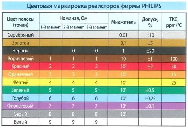
Another way to decrypt the color code from Philips involves the use of 4, 5 and 6 bands. Then the last strip carries information about the temperature coefficient of resistance (how much the resistance changes with temperature).
To determine the face value, use the table. Pay attention to the last column - this is TCS.
On the case, colored rings are distributed, as shown in this diagram:
You can learn more about how to decipher the marking of resistors from the video data:
Marking SMD Resistors
In modern electronics, one of the key factors in the development of a device is its miniaturization. This causes the creation of leadless elements. SMD components are small due to their lead-free design. Do not be confused by this installation method, it is used in most modern electronics and has good reliability. In addition, this simplifies the design of the multilayer printed circuit board. Literal interpretation with translation means "surface mounting device", and they are mounted on the surface of the printed circuit board. Due to the miniature size, difficulties arise with the designation of their face value and characteristics on the case, therefore they compromise and use marking methods by numbers, with letters or using a code system. Let's see how SMD resistors are labeled.
If 3 digits are applied to the SMD resistor, then the decryption is performed as follows: XYZ, where X and Y are the first two digits of the nominal, and Z is the number of zeros. Let's look at an example.
4-digit designation is possible, then everything is the same way, only the first three digits are hundreds, tens and ones, and the last is zeros.
If letters are entered in the marking, then the decoding is similar to domestic MLT resistors.
And integers are separated from fractional values.
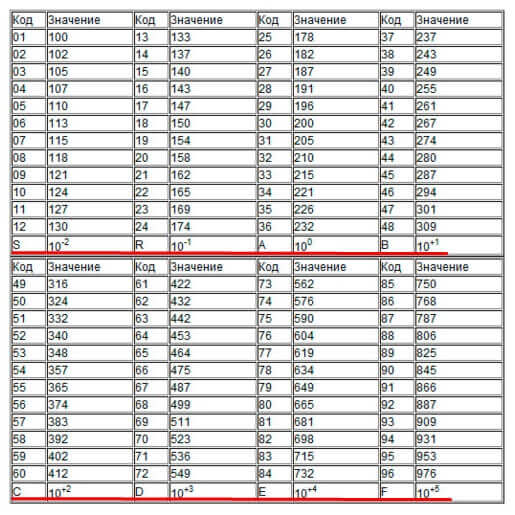
Another thing when using alphanumeric coding, such resistors have to be decrypted according to the tables.
In this case, the letter denotes the multiplier. In the table below, they are circled in red.
Based on the table, the code 01C means:
- 01 = 100 ohms;
- C - factor 102it is 100;
- 100 * 100 = 10000 Ohm or 10 kOhm.
This designation is called EIA-96.
The information contained in a character or color coding will help you build circuits with high accuracy and use elements with appropriate ratings and tolerances. A proper understanding of the notation will not save you from the need to measure resistances. It’s still better to check it again, because the element may be defective. Checking can be done with a special ohmmeter or multimeter. We hope that the information provided on what labeling of resistors can be and how it is decoded was useful and interesting for you!
Similar materials:









Good afternoon !
Everything is beautifully told about color marking, but what if the marking does not correspond to the given table?
1) there are 5 color rings evenly distributed along the length
2) colors: black - golden (brown?) - white - black - green
or so: green - black - white - golden (brown?) - black
3) result = ???
Hello! If the strip is golden, it is probably 500 MΩ, if brown is 5 kΩ.
You can not check the resistance with a multimeter? Also note that this may not be a resistor, but an inductance, for example.
Good afternoon !
Thanks for the answer. But it became even more incomprehensible. Is the 4th band a multiplier? If it is black, then 1, if golden - 1/10 (although you don’t have that color in the first table), if brown - 10. The difference is 100 times. You indicated a difference of 100,000.
To avoid some issues:
1) a part from a Chinese musical toy, so there’s no question of searching the Internet for standard circuits
2) the part is broken, so it is impossible to measure
3) the Chinese are still generous with paint and there are letters “R3” on the board in this place, so inductance is unlikely
4) according to the scheme, it is very similar to a quenching resistance, so even 5 kOhm is hardly possible. Although, these are the Chinese ...
I know very well that I indicated a huge difference, but you yourself already see that the definition according to the tables is not always so unambiguous, especially since it is not always possible to accurately identify the color, as in your case. I gave approximate values from the tables and other tables indicated in the article, for some reason they differ in this way, maybe they depend on the specific type of resistor. In one of the tables, the marking is indicated for resistors filled with stripes evenly, black is generally 0, brown (no gold) is 1, white is 9, black is x1, green is 0.5%, that is, generally 19 Ohms with tolerance half a percent.
If you read in the opposite direction, then: green - 5, black - 0, white - 9, brown - x10, but then the tolerance cannot be indicated in black - suggests that reading in this order is incorrect.
According to the marking of resistors from philips films: black - for the first strip no, brown - 1 (no gold) - 1, white - 9, black - x1, green - 0.5%, that is, in general 19 Ohms with a tolerance of half percent, as well as in the previous table (maybe it's the same, but more unified).
If in the opposite direction, then again 509 * 10 = 5 kOhm, but here the tolerance of 20% is indicated in black
In short, do not look - you need to try 5 kOhm. And in order not to give up the circuit, I would take a 5 kΩ resistor and sequentially take a potentiometer as much as possible (you might not find 500 MΩ), then put it into maximum resistance, connect it to the circuit and start to decrease the resistance, observing the current consumption or at least a fee for heating (unless of course there is no 220V). But still I think it's 5 kOhm.
Hi guru! the diagram indicates R3 with a rating of 8.2E and PR1 of 1.6K. With the latter, the question seems to be a clear, variable resistor, but the first? Tell me please
Hello, I have such a case where the designation R15A is SMD designation 110 is correct. As I understand it, the R15A resistor should be 0.15 Ohms and the SMD 1 Ohm the question is how do I find the R15A resistor to unsolder
What does it mean "R15A designation costs SMD designation 110 is correct"?
R15 is 0.15 ohms. And this is the letter "A" - it is not entirely clear. Is this a resistor? How to find? I don’t know how to find it, I don’t know what donors you have ... Order a pack for Ali-Express - there’s a penny.
Hello, there is the task of counting DHM in products. In fact, we see the designation of resistors such as 3k9, 4k3,1k1, etc.How to translate such designations into a readable type C2-14-0.125 (10-98.8) OM, so that you can use the directory?
no way. You confuse the denomination with the series designation. In some cases, it can only be visually determined.