What is the resonance of currents and voltages
Inductance reactance and capacitance
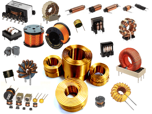
Inductance is the ability of the body to accumulate energy in a magnetic field. It is characterized by a lag of current from voltage in phase. Typical inductive elements are chokes, coils, transformers, electric motors.
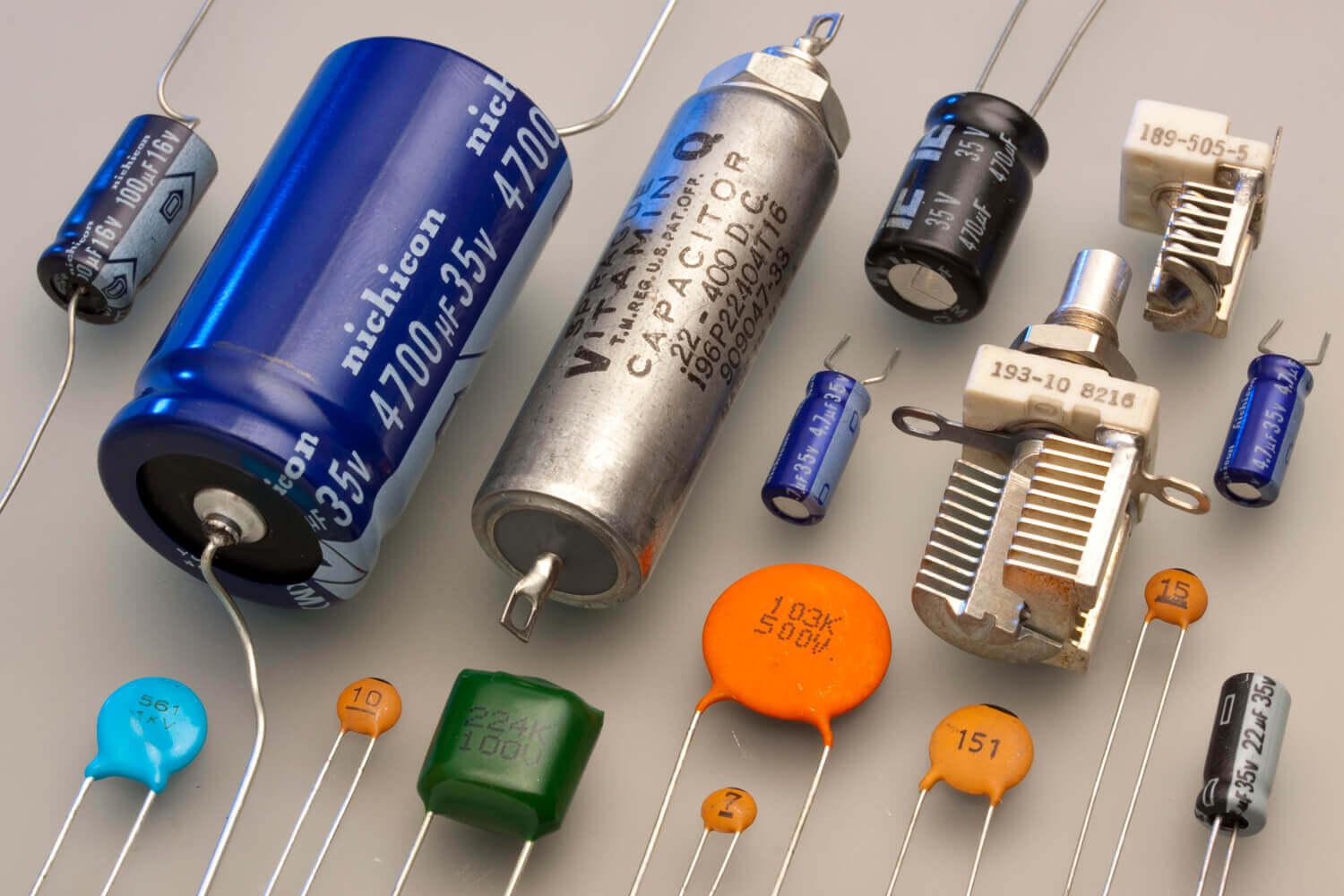
Capacity refers to elements that store energy through an electric field. Capacitive elements are characterized by a phase lag of voltage from current. Capacitive elements: capacitors, varicaps.
Their basic properties are given, the nuances within this article are not taken into account.
In addition to the listed elements, others also have a certain inductance and capacitance, for example, in electric cables distributed along its length.
Capacitance and inductance in an alternating current circuit
If in direct current circuits the capacitance in the general sense is a broken part of the circuit, and the inductance is a conductor, then in alternating capacitors and coils are a reactive analog of a resistor.
The reactance of the inductor is determined by the formula:
Vector diagram:
Capacitor reactance:
Here w is the angular frequency, f is the frequency in the sinusoidal current circuit, L is the inductance, C is the capacitance.
Vector diagram:
It is worth noting that in the calculation of reactive elements connected in series, the formula is used:
Please note that the capacitive component is taken with a minus sign. If the active component (resistor) is also present in the circuit, then add according to the formula of the Pythagorean theorem (based on the vector diagram):
What does reactance depend on? Reactive characteristics depend on the value of capacitance or inductance, as well as on the frequency of the alternating current.
If you look at the formula of the reactive component, you can see that for certain values of the capacitive or inductive component, their difference will be zero, then only the resistance will remain in the circuit. But these are not all the features of such a situation.
Voltage resonance
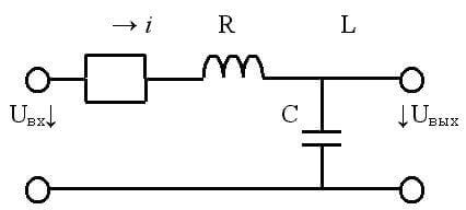
If a capacitor and an inductor are connected in series with a generator, then, provided that their reactance is equal, a voltage resonance will occur. In this case, the active part Z should be as small as possible.
It is worth noting that inductance and capacitance have only reactive qualities only in idealized examples. In real circuits and elements, active resistance of conductors is always present, although it is extremely small.
At resonance, an energy exchange occurs between the inductor and the capacitor. In ideal examples, during the initial connection of an energy source (generator), energy is accumulated in the capacitor (or inductor) and after it is switched off, undamped oscillations occur due to this exchange.
The voltages at the inductors and capacitances are approximately the same, according to Ohm's law:
U = I / X
Where X is the Xc capacitive or XL inductance, respectively.
A circuit consisting of inductance and capacitance is called an oscillatory circuit. Its frequency is calculated by the formula:
The oscillation period is determined by the Thompson formula:
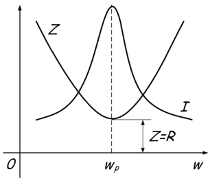
Since the reactance depends on the frequency, the inductance resistance increases with increasing frequency, and decreases at the capacitance. When the resistances are equal, the total resistance is greatly reduced, which is reflected in the graph:
The main characteristics of the circuit are the quality factor (Q) and frequency. If we consider the circuit as a four-terminal, then its transmission coefficient after simple calculations is reduced to the quality factor:
K = q
And the voltage at the terminals of the circuit increases in proportion to the transfer coefficient (quality factor) of the circuit.
UK = Uin * Q
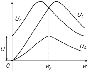
With voltage resonance, the higher the quality factor, the greater the voltage on the circuit elements will exceed the voltage of the connected generator. The voltage can increase tens or hundreds of times. This is shown in the graph:
Power losses in the circuit are due only to the presence of active resistance. Energy from the power source is taken only to maintain fluctuations.
The power factor will be equal to:
cosФ = 1
This formula shows that losses occur due to active power:
S = P / Cosph
Resonance currents
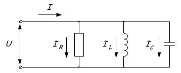
Current resonance is observed in circuits where the inductance and capacitance are connected in parallel.
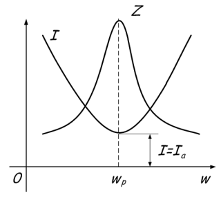
The phenomenon consists in the flow of large currents between the capacitor and the coil, at zero current in the unbranched part of the circuit. This is because when the resonance frequency is reached, the total resistance Z increases. Or in simple terms it sounds like this - at the resonance point the maximum total value of the resistance Z is reached, after which one of the resistances increases and the other decreases depending on whether the frequency increases or decreases. This is graphically displayed:
In general, everything is similar to the previous phenomenon, the conditions for the emergence of current resonance are as follows:
- The power frequency is similar to the resonant at the circuit.
- The conductivities of the inductance and capacitance for alternating current are equal to BL = Bc, B = 1 / X.
Practical application
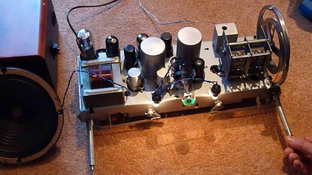
Consider the benefits and harms of resonance currents and voltages. The greatest benefit of the phenomenon of resonance brought in radio transmitting equipment. In simple words, the receiver circuit has a coil and a capacitor connected to the antenna. By changing the inductance (for example, moving the core) or the value of the capacitance (for example, an air variable capacitor) you adjust the resonant frequency. As a result, the voltage on the coil rises and the receiver catches a certain radio wave.
These phenomena can be harmful in electrical engineering, for example, on cable lines. A cable is an inductance and capacitance distributed along the length if voltage is applied to a long line in idle mode (when the load is not connected to the end of the cable opposite the power source). Therefore, there is a danger that a breakdown of insulation will occur, in order to avoid this, a load ballast is connected.Also, a similar situation can lead to failure of electronic components, measuring instruments and other electrical equipment - these are dangerous consequences of this phenomenon.
Conclusion
The resonance of voltages and currents is an interesting phenomenon to be aware of. It is observed only in inductive-capacitive circuits. In circuits with large active resistances, it cannot occur. To summarize, briefly answering the main questions on this topic:
- Where and in which chains is the resonance phenomenon observed?
In inductive capacitive circuits.
- What are the conditions for the occurrence of resonance of currents and voltages?
It occurs under the condition of equal reactance. The circuit must have a minimum active resistance, and the frequency of the power supply coincides with the resonant frequency of the circuit.
- How to find the resonant frequency?
In both cases, by the formula:w = (1 / LC) ^ (1/2)
- How to eliminate the phenomenon?
By increasing the resistance in the circuit or changing the frequency.
Now you know what the resonance of currents and voltages is, what are the conditions for its occurrence and practical applications. To consolidate the material, we recommend watching a useful video on the topic:
Related materials:

