Methods and schemes for braking electric motors
Electric motor braking is used if it is necessary to reduce the free-running time and fixing the mechanism in a specific position. There are several types of forced stopping of the device. It is mechanical, electrical and combined. The mechanical device is a brake pulley mounted on a shaft with pads. After disconnecting the device, the pads are pressed against the pulley. Due to friction, kinetic energy is converted into heat, i.e. there is a braking process. Other methods and schemes for braking an electric motor will be discussed later in the article.
Electric braking methods for electric drives
In order to quickly stop the device or to provide a constant speed of rotation, electric stop methods are used. Depending on the switching circuit, the brake modes are divided into:
- opposition;
- dynamic;
- regenerative.
Opposition
Opposition mode is applied when a quick stop is necessary. Represents a change in polarity on the winding of the armature of a DC motor or switching two phases on the windings induction motor.
In this case, the rotor rotates in the opposite direction of the stator magnetic field. The rotation of the rotor slows down. When the rotation speed is close to zero, a signal is received from the speed control relay, disconnecting the mechanism from the network.
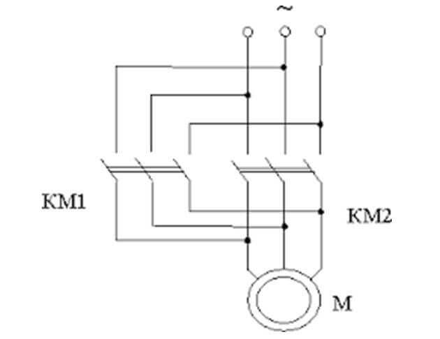
The figure below shows the opposition circuit of an asynchronous electric motor.
After switching the windings, an increased effective voltage and an increase in current occur. For its limitation, in windings rotor or stator establish additional resistors. They limit the currents in the windings in braking mode.
Drive dynamic stop
This method is used on asynchronous machines connected to AC power. It consists in disconnecting the windings from the AC voltage network and supplying direct current to the stator winding.
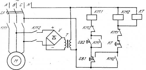
The above figure shows a braking scheme for a three-phase DC motor.
DC voltage is supplied using a step-down transformer for dynamic braking. Undervoltage AC to DC diode bridge and fed to the stator winding. An additional DC source can be used to brake the electric motor.
In this case, the rotor can be made in the form of a "squirrel cage" or its winding is connected to additional resistors.
Constant voltage creates a stationary magnetic flux.When the rotor rotates in it Emf, i.e. the electric motor goes into generator mode. The resulting electromotive force is dissipated on the rotor winding and additional resistors. A braking moment is created. When the mechanism stops, the constant voltage is switched off by the signal of the speed relay.
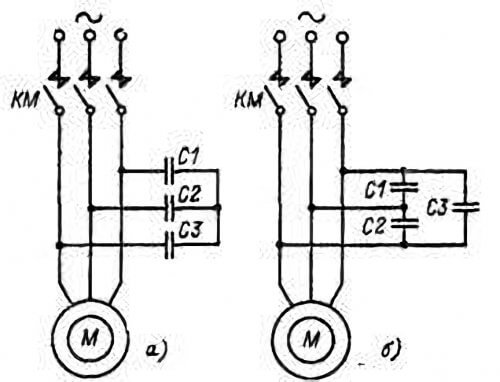
Mechanisms where an electric motor with self-excitation is used, a dynamic stop is performed by connecting capacitors. They are connected by a triangle or a star.
The diagram is shown in the figure below.
On coasting, the residual energy of the magnetic field passes into the charge of the capacitors, and then it feeds the stator winding. The resulting braking effect stops the mechanism. The capacitor bank can be connected continuously or connected at the time of disconnection from the network. Such a scheme is called "capacitor braking of an induction motor."
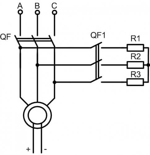
If it is necessary to quickly stop the engine, then after disconnecting from the network, short-circuit the contacts without quenching resistors. When connecting the windings by shorting, large currents arise in them. To reduce currents, current limiting resistors are connected to the windings.
The figure below shows a circuit with current limiting resistors.
Braking modes of DC motors
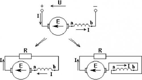
Dynamic braking of the DC motor is carried out after disconnecting it from the network with the closure of the rotor winding on the brake rheostat. The released electrical energy is dissipated on the rheostat.
The above figure shows the rheostatic braking circuit of a DC motor.
Regenerative braking of electrical machines
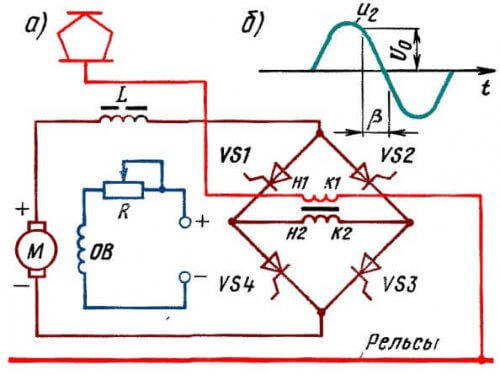
Regenerative braking of the electric motor is characterized by the transfer of the motor to the generator mode. In this case, the generated electricity is returned to the network or used to recharge the battery.
This mode is widely used in electric locomotives, trains, trams and trolleybuses. At the time of braking, the generated electricity returns to the electrical network.
Regenerative braking mode is used to recharge batteries in hybrid cars, electric cars, electric scooters, electric bicycles.
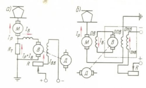
This mode is the most economical and possible under the condition: if the rotor speed exceeds the idle speed. This condition is satisfied when the EMF of the electric motor exceeds the supply voltage. And the armature current and magnetic flux change their direction. The electric machine goes into generator mode, there is a braking moment.
The figure shows the braking circuit of the traction engine a) with independent excitation and stabilizing resistance, b) with anti-excitation of the pathogen.
Regeneration mode in asynchronous electric machines
Regeneration mode is used not only in DC motors. It can also be used in induction motors.
Moreover, this mode is possible in the following cases:
- If you change the frequency of the supply voltage with frequency converter. What is possible if the induction motor is powered from the device with the ability to control the frequency of the supply network. The braking effect occurs when the frequency of the supply voltage decreases. In this case, the transition to the generator mode occurs when the rotor speed becomes greater than the nominal (synchronous).
- Asynchronous machines, which structurally have the ability to switch windings, to change the speed.
- In hoisting mechanisms where power descent is used. They mounted an electric motor with a phase rotor. In this case, the speed is controlled by changing the value of the resistor connected to the rotor windings. The magnetic flux begins to overtake the stator field, and the slip becomes greater than 1.The electric motor goes into generator mode, the generated electricity is returned to the network, there is a braking effect.
Combined mode
Combined braking modes are used in electric machines, if you need to quickly stop and lock the mechanism. To do this, use a mechanical braking unit in combination with electric braking. The combination may be different. This can be an electrical circuit with an opposition, dynamic and regenerative modes.
So we examined the main methods and schemes for braking electric motors. If you have questions, ask them in the comments under the article!
Related materials:

