Connection diagram of test box with current transformers
What is important to know
Requirements for devices and switching circuits are indicated in GOST. Manufacturers cannot depart from these requirements, since metering devices must be certified accordingly and pass state verification. So, for example, according to clauses 4.1 and 4.2 of GOST 31818.11-2012 (IEC 62052-11: 2003), standard and allowable voltage and current values are determined for direct and transformer connection meters. The most commonly used in 0.23 and 0, 4 kV networks are direct-connected meters and transformer-connected meters with current transformers. Voltage transformers are usually used in electrical installations with a higher voltage level.
Direct inclusion counters according to the specified GOST have standard values of currents of base and rated currents of 5, 10, 15, 20, 30, 40, 50 A and permissible values of currents are 25, 80, 100 A.
For current transformer meters, the standard current values are set to 1, 3, 5 A. The permissible current values for such meters are 0.2; 0.3; 0.6; 1.0; 1.5; 2.0; 2.5; 5.0; 10.0 A.
What does the standard and permissible current value mean? The standard value of the base current is used for meters with direct connection - it is the initial one to establish the requirements for this type of meters.
The standard value of the rated current is used for meters working through a transformer, and the rated current of the meter must be equal to the rated current of the secondary winding of the current transformer. This requirement is given in clause 1.5.19 of the EMP (Chapter 1.5).
Allowable currents contain a wider range of data. Atchoosing current transformers and counters pay attention to these nuances.
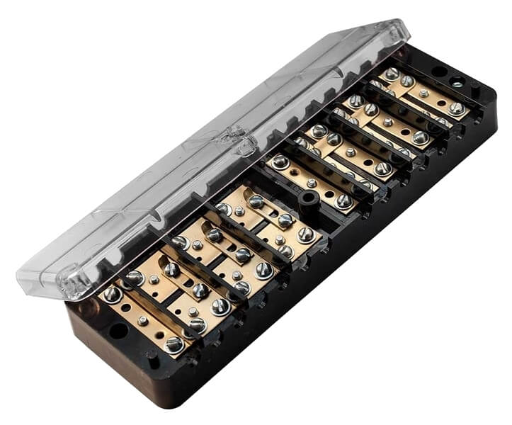
Electricity meters can be turned on using a test box. In PUE p. 1.5.23, it is recommended that metering circuits be constructed for independent assembly of clamps or sections in a common row of clamps. If this is not possible, then test boxes are used for metering circuits. During installation, it is necessary to ensure the shorting of the secondary windings of current transformers when they are checked or replaced. The current circuits of the meters and voltage circuits in each phase must be disconnected without disconnecting the wires and cables.
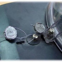
Without fail, in accordance with the same clause of the PUE, test boxes and clamp assemblies should be able to be sealed.
The design of the KIC should include the ability to connect a reference meter.
Installation diagram
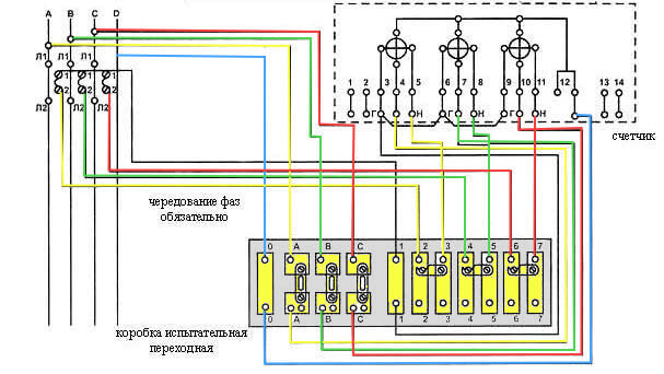
The figure below shows the electrical circuit for connecting the meter through the test terminal box:
As can be seen from the diagram, a terminal connected to the three-phase power source via current transformers comes to the terminals in the block marked A, B, C. The neutral wire is connected to a separate terminal. Further, from these terminals using the wires connected metering device in compliance with the following conditions:
- transformers are connected according to the star circuit, and their common output is grounded;
- from current converters to the junction box, wires with a cross section of at least 1.5 mm² are laid;
- Three wires with a cross section of 2.5 mm² are connected from the metering device
- for convenience, everything wires are marked - three phases and the beginning of current windings and a general conclusion are indicated.
Since the circuit does not imply direct contact between the terminals of the current transformers and the terminals of the meter, it is necessary to monitor the sequence of switching on.
The counter terminals are connected in the following order:
- A wire from the current winding of the first phase transformer is connected to 1 terminal
- a wire is connected to the second terminal of the meter - voltage of the first phase;
- the wire from the current winding of the second phase is connected to the 4 terminal of the meter;
- 5 connects the voltage of the second phase;
- 7 - incoming wire of the current winding of the third phase;
- 8 - voltage of the third phase;
- 9 - common wire;
- 10 - reserve.
Between the third and sixth terminals, as well as between the sixth and ninth, jumpers are installed in the counter.
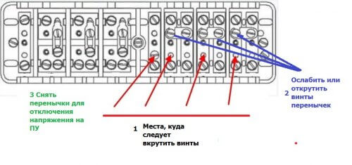
For safe counter removal it is necessary to bypass the current circuit to ensure reliable contact between the box screws and the insulated busbar. This bus is located on the rear side and by tightening the screws, as shown in Figure 2, you will ensure contact.
Next, loosen the jumper screws to open the jumpers. After that, remove the jumpers from the power section to disconnect the voltage at the meter terminals. Next, the counter is turned off and off. Connection is in the reverse order.
We also recommend that you watch the video, which clearly demonstrates the various ways of connecting the KIC box to the electricity meter:
We hope that this article was informative and now you know how to connect the test box to the meter. For all questions, please contact the forum or in the comments under the post!
Surely you do not know:



Hello!
I apologize for being rude, some kind of turbidity ... The scheme is correct, but the photo of the shield: the assembly is working, but only to replace the counter, and where to pick up the reference counter. Although the receiving energy shields often require just such an exclusion scheme, apparently due to their ignorance of the correct scheme.
Exactly, dregs. And the explanation of how to relieve tension is muddy. Voltage is not removed by jumpers. A normal person will not climb a 380 V screwdriver into a box.
Hello! The editors are open for dialogue, indicate specifically the shortcomings of the article, the authors will correct them.
Good afternoon! There are no flaws in the article, everything is extremely clear. Just the very concept of the authors of this device about the "safe" work with the box is crazy. An accidental touch on the terminals or an awkward movement with a screwdriver - that’s 380 volts for you. Insulator cardboard - I'm paying ... Carry M4 screws and screw them in, hoping that something will be shunted into the "blind" ...
Alexander, good afternoon!
And what do you say about such an example.
Got a cabinet with mounted metering unit through the box.
They turned it on, started working, but over time they noticed that consumption was low on the meter.
The counter scheme is Mercury 230, the installed box and the circuit are understandable. As a result, shunts (invisible) were installed in the box and it was required to unscrew them by unscrewing the bolts in the box.in the description on the box diagram, there is nothing about shunting. Who should clean their brains?
The voltage is removed after removing the load on the test box (screwing in the shunts), shorting the jumpers, and removing / raising the jumpers to IR voltage
The scheme is fundamentally wrong.
The circuits from the CTs are connected fundamentally wrong. The main task of the Test box is to short-circuit the current circuits on the CT in case of disconnection from the meter. This will protect the CTs from overload and leave other devices connected to these CTs in operation. In the diagram, when switching by jumpers, the current circuits will be broken, CTs will burn out due to overvoltage.
TT chains are through. A jumper is placed between the neutral and 3 CT outputs on the input side of the box. When switching a jumper, the current circuits to the meter must be broken and shorted to neutral.
Poorly(.
We connect German sp. boxes, Weidemüller - heaven and earth. Instead of the left part of the circuit, where on the bolts of the jumper to relieve tension there is just AB 4p, I turned it off and that’s all, you do not need to turn any bolts under voltage. For the right side of the circuit, plug-in insulated jumpers are used to short-circuit the secondary windings of the CTs, they are similar in shape to atomic fuses, everything is simple and logical, you do not need to invent this clumsy bicycle, Well, shorting the secondary circuits of the TT by screwing in the bolts is something with something. It’s a pity I can’t take a photo, I’d even appreciate it and feel the difference 🙂
Weidmuller is very beautiful, very comfortable ... ... and very expensive .... when it comes to one - five metering stations - and God would have been with him ....... I have 270 writhing here.
That's right. The Germans even thought over the little things. This significantly increases productivity during installation.