How to connect a magnetic starter - instructions with diagrams
Options Overview
In manual mode, the inclusion is made from the button post. The start button opens an open contact for closing, and the stop works for opening. The self-pickup magnetic starter wiring diagram is as follows:
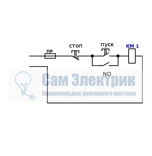 Consider the operation of the on and off circuits of a magnetic contactor. A two-button push-button post, when START is pressed, the phase enters from the network through the STOP contacts, the circuit is assembled, the starter retracts and closes the contacts, including additional NO, which is parallel to the START button. Now if you let go of it, the magnetic starter continues to work until the voltage disappears or trips thermal relay P motor protection. When STOP is pressed, the circuit breaks, the contactor returns to its original position and the contacts open. Depending on the purpose, the coil power can be 220v (phase and zero) or 380v (two phases), the principle of operation of the control circuits does not change. The inclusion of a three-phase electric motor with a thermal relay through a push-button post is as follows:
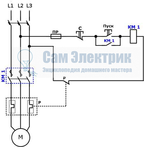
In the end, it looks something like this, in the picture:
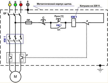
If you want to connect a three-phase motor through a magnetic starter with a 220 volt coil, you need to perform the switching according to the following wiring diagram:
Using the three buttons on the control panel, you can organize the reverse rotation of the electric motor.
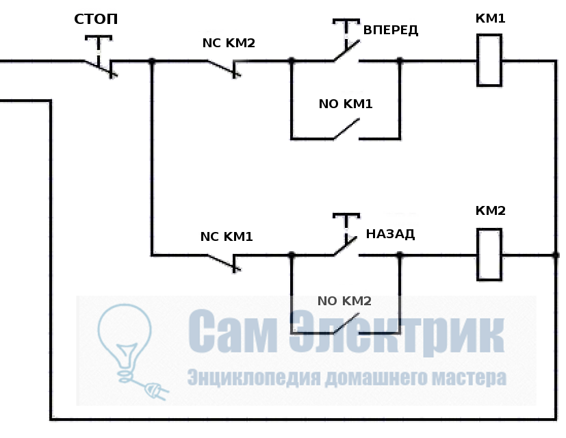
If you look closely, you can see that it consists of two elements of the previous scheme. When START is pressed, contactor KM1 turns on, closing NO KM1 contacts, becoming self-locking, and opening NC KM1 eliminating the possibility of switching on contactor KM2. When the STOP button is pressed, the circuit is disassembled. Another interesting element of the three-phase reversible connection scheme is the power unit.
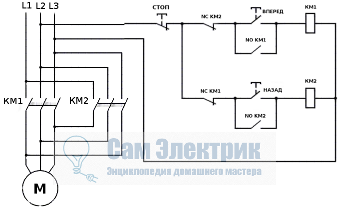
At the contactor KM2, the phases L1 are replaced by L3, and L3 by L1, thus changing the direction of rotation of the electric motor. In principle, this three-phase and single-phase load control circuitry covers the domestic needs with a head, and is easy to understand. You can also connect additional elements of automation, protection, limiters. Consider all of them separately for each specific device.
Using the above connection diagram of the magnetic starter, you can organize the opening of the garage door by introducing additional limit switches into the circuit, using NC contacts in series with NC KM1 and NC KM2, limiting the movement of the mechanism.
Connection Instructions
The easiest connection option is through the button. In this case, you need to act as shown in the video:
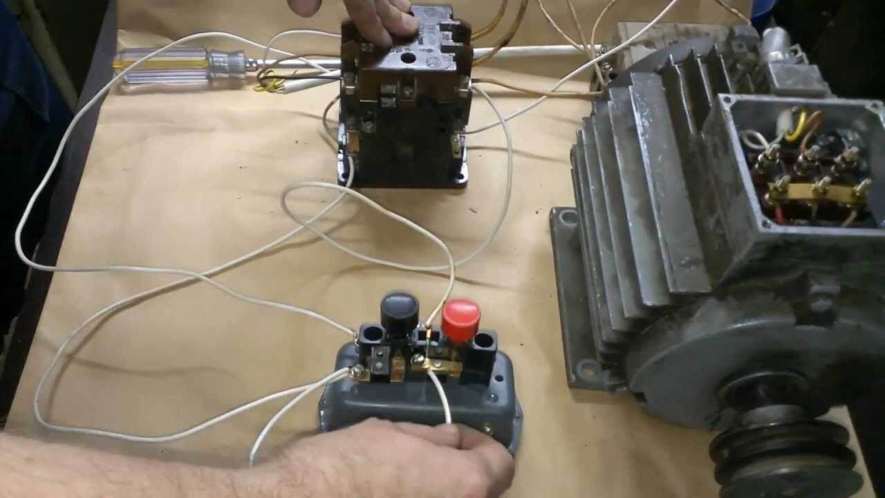
For an example with an engine, it looks like this:
The motor can be connected using a reverse circuit as follows:
Here by this principle, you can independently connect the device to a network of 220 and 380 volts. We hope that our instructions for connecting a magnetic starter with circuits and detailed video examples were understandable and useful for you!
It will be interesting to read:




Hello. Question? can either the motor be connected without the contact block on the button? if it is replaced with a button with a latch. motor coil for 220 rotation in one direction only, is it possible? It will be good or bad. Why is the latch button bad? My name is Igor, I will be very glad to answer
Hello! The block contact is also needed for fixation.
Therefore, you said everything correctly - replace with a latch button or a toggle switch. The contact block will simply leave the circuit and the button will be replaced with what I wrote above.