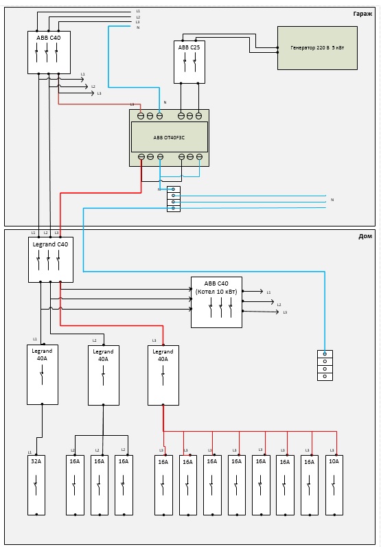
Is the correct connection diagram of the generator to the network of a country house?
I re-read various articles on the topic, and all the same, doubts remain. Help me please. The task is to connect the generator to the network of a country house. The generator is in the garage, the exhaust pipe is facing the street. In the garage there is an entrance distribution panel, a cable comes from a pole to it, from it there is a wiring to a house, a bathhouse, a garage and so on. I will connect the generator only to the house. Bathhouse, garage, etc. is not connected. In the house, not everything must be connected to the generator (the generator will not withstand the boiler for 10 kW). Switching the switch and starting / disabling the generator will be manual (no autostart). I drew a diagram here (as I understand it should be).
The order of inclusion - turned on the generator, then threw the switch.
After applying voltage to the network, consumers connected by other phases (L1, L2) will work. This is a signal to go off the generator. Accordingly, I switch the switch, turn off the generator. Everything seems to be simple.
Questions and doubts that remain:
- There is doubt - is it possible. After the network turns on, will the generator burn out? Because the switch switches both phase and zero, and zero is common to all phases.
- When switching to a generator, is it necessary to turn off the boiler? Because all 3 phases are connected to it, and after turning on the generator, only one of them will work.
Tell me, please, is everything right in my schemes / designs. Or direct on the true path :). Thank.


An interesting solution, and I think it will work, the only caveat is the inclusion of heating elements in the boiler, they must be with a common zero star circuit. A voltage signaling device is better to do of a different type. But not suddenly supplying voltage to consumers in the house.
You need to disconnect all three phases, and after switching the generator, a common zero is good. To signal voltage, make a light or sound indicator.
“0” of the generator to the common “0” of the bus in the shield (I hope it is!), And not in the reversing switch. The remaining poles at the input of the switch are jumpers.