What are the faults of voltage stabilizers and how to repair them
Buzz and clicks
If the voltage regulator is humming heavily, you need to check that the supply voltage is not above or below the acceptable ranges. The adjustment range in most cases lies within 100-250 Volts.
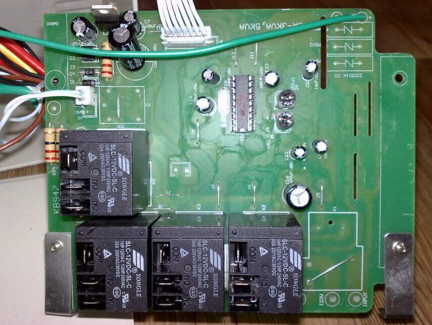
Attention! Even with a good condition, the autotransformer evenly and not too loudly buzzes. The hum also emits a servo when moving the brush assembly. Relay voltage stabilizers emit clicks during operation. This is normal, relays (black rectangles in the figure below) switch the taps from the windings to adjust the output voltage.
If the device pops loudly, this may indicate brush sparking in the servo-drive models, problems with the relay, and poor contact of the device’s internal wiring.
Turns off under load
The voltage regulator does not hold the load - this problem happens for a number of reasons. The first among them is an increased load (consumer power). If you have not changed the connected devices, then the problem is the stabilizer. If it does not turn off immediately, but after some time, then this may be due to overheating or inter-turn autotransformer short circuits.
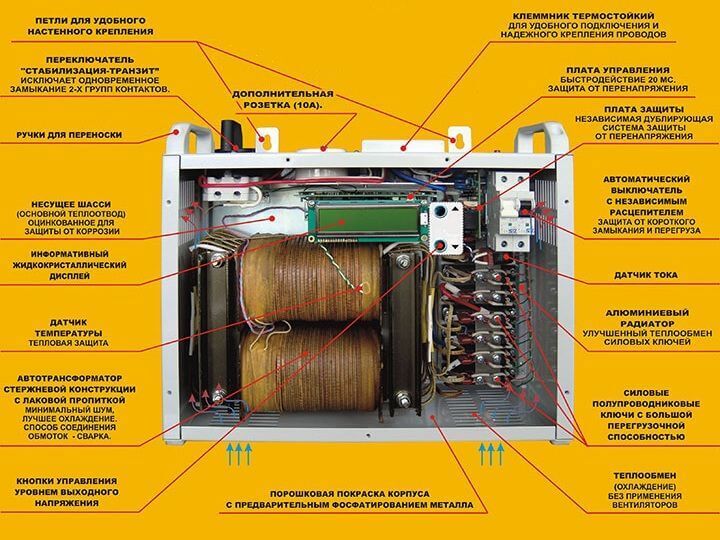
What to do: disassemble the device and conduct an external inspection of the autotransformer windings, if it is not too dusty, then check for signs of local overheating. If there is a lot of dust, clean it
If there are traces of overheating and burning, the insulation of the windings is damaged. This is the inter-turn circuit, then how to repair the stabilizer in this case? It is necessary to rewind or replace the autotransformer with a similar or higher power. But the cost of such repairs can be comparable to buying a new voltage regulator.
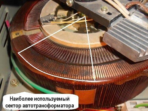
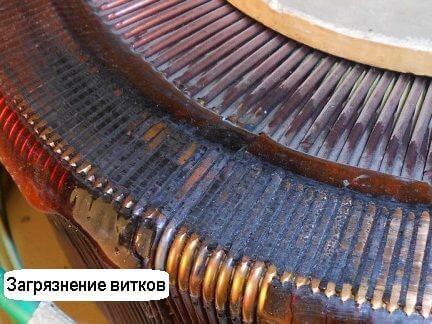
Important! In servo-driven models, a number of malfunctions can be caused by brush wear and contamination of live parts with graphite chips. In the process, the brush is erased, falling asleep with graphite autotransformer. Because of what, short circuits can occur between current collectors and turns and overheating. In this case, you need to sweep the graphite and clean it between the turns. Make sure that the windings are laid evenly, that there are no breaks. Strip the contact surface with an ordinary stationery eraser to a shine, especially the most used sector.
There is no 220 volt output
The malfunction is manifested in the fact that the stabilizer does not give out a voltage of 220 volts. This does not necessarily indicate internal problems, the cause may be the mains voltage - it is too low, and the device simply does not pull. If the power is in the operating range of the stabilizer, then proceed with the repair.
What to do: in servo-driven models, damage can be caused by wear on the brush mechanism or on the servo itself. It may not reach the end of the winding or the brush may not be in contact with its corresponding sector. In the simplest case, it can simply be contaminated with graphite. To repair it, you need to clean the surface of the contacts to a metallic luster. Sometimes you need to replace the brush.
Interesting! It also happens that due to contamination of the working sector of the brush assembly with graphite, often the voltage does not rise above a certain value.
In relay SNs, this most often indicates that one or more electromagnetic relays or a cascade of their control are faulty. Usually it is built on a transistor. Relays can have different coil voltages, often 12 volts.
What to do: to check, apply voltage to the coil and ring the power contacts. They must close and open, while the relay clicks. If this does not happen, either the contacts stick (more often), or the relay coil burns out (less often). If the relay is OK - check transistor, it should not be punched, and the emitter-base and collector-base junctions should be dialed in one direction, like a diode. Transistors use any low-power similar conductivity.
In triac and thyristor CH, the diagnosis of failure is similar - you need to ring the semiconductor power switch for a breakdown and if it fails, replace it with a similar or more powerful one.
Poor voltage stabilization
If the voltage is stabilized in too large steps, and before everything was smooth, then the breakdown is close to the previous one - the switching device at one or several adjustment steps failed. The algorithm for checking the failure of the voltage regulator and their elimination are described in the previous paragraph.
Attention! In the characteristics of each of the stabilizers, either an adjustment step or the boundaries of each stage are described, as well as the accuracy of maintaining the rated output voltage.
In servo-driven stabilizers, this occurs in the event of a breakdown in the mechanism of the engine gearbox, as well as when the windings are dirty, as was the case described above. Gearbox malfunctions can be accompanied by uneven buzzing or cracking - this gears slip.
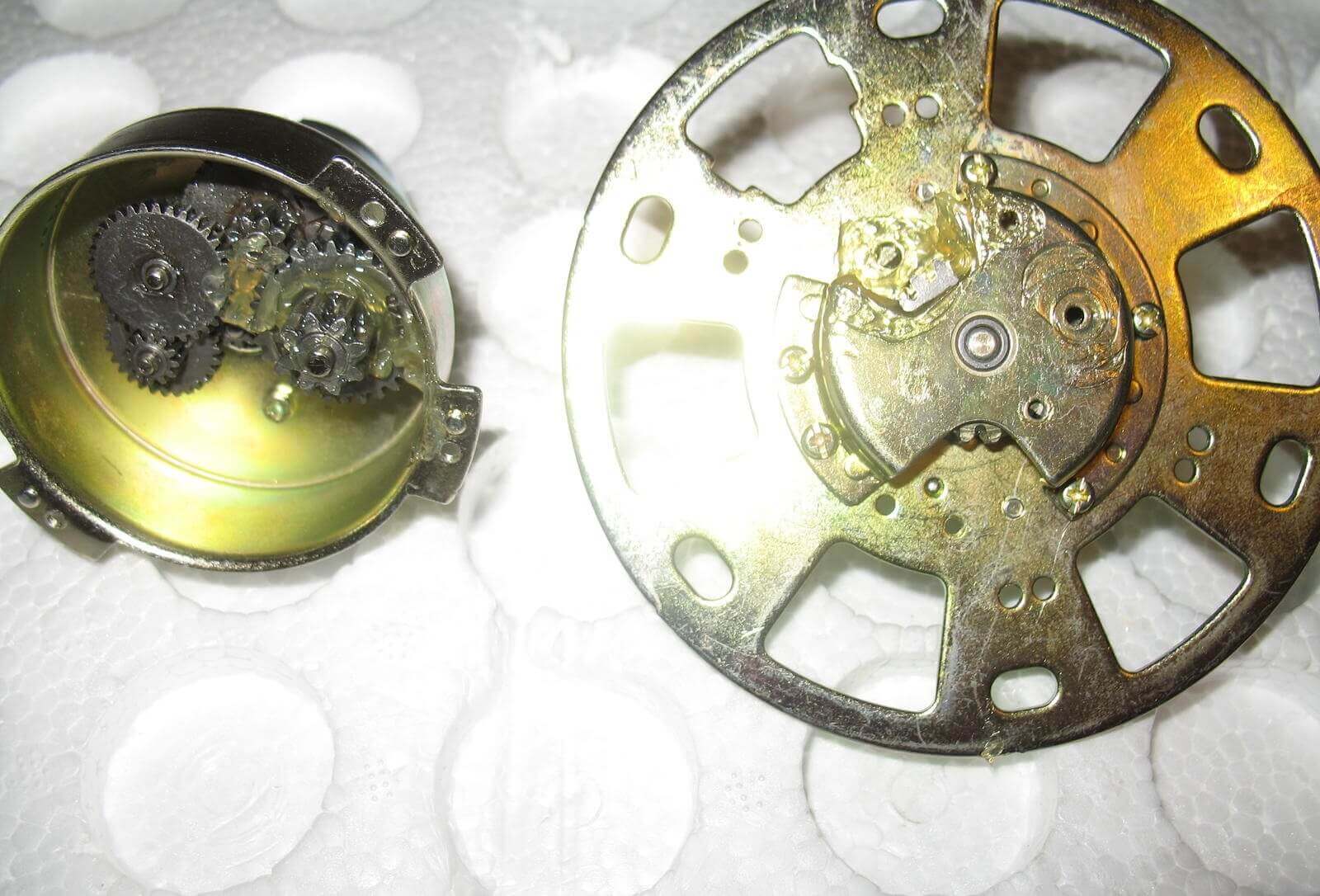
What to do: you need to disassemble the mechanism and if all the parts are normal, replace the grease.
It is also worth noting that for servo-driven CHs stabilization may be absent, it may not work correctly due to the failure of semiconductor motor control keys. Then the slider with the brush moves to one of the extreme positions or does not move at all.
It does not turn on or knocks the machine after a timer report
Most stabilizers after switching on enter the operating mode not immediately, but after a time delay. But after the report, the reverse start timer does not occur, while the display shows the letter N. An example of repairing a device with such a malfunction is considered in the following videos:
For information, the error code "H" indicates an overvoltage of the network and the operation of protection.This is true for appliances from Resanta, Luxeon and some others.
Interesting: the letter “H” means “High” or “High”, and L means “low”, “Low”. Resistor, the replacement of which you saw in the video, is responsible for the thresholds for the upper and lower voltage levels. Due to incorrect resistance, the stabilization board does not cope with its work and goes into defense.
Such symptoms or another malfunction code may be accompanied by a knockout of the machine feeding the stabilizer itself after a report of the on-delay timer. In this case, the problem is solved by replacing the relay, during sticking of which an increased current consumption can occur.
It shows no signs of life or other damage
The most frightening malfunction is when, after applying the voltage, neither the indicators light up, nor the output voltage appears, i.e. when the voltage regulator does not work at all. In this case, the control board may fail. Most often, repairs begin with a visual inspection, pay attention to:
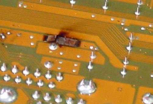
- burnt paths;
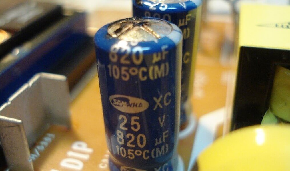
- bloated electrolytic capacitors;
- burned out, cracked, or exploded board components;
- microcracks on soldered contacts and cold soldering.
All the identified shortcomings are eliminated, and if the external examination does not give results, they go on to check the board for broken tracks and short circuits with a multimeter in the mode of measuring resistance and continuity. Such a repair of the stabilizer may require a deep knowledge of electronics, the electrical circuit diagram, and in the most difficult cases, the use of an oscilloscope to check the control signals and the logic of the circuit.
That's all we wanted to tell you about the faults of voltage regulators and how to fix them with our own hands. We hope that now you know what to do in this or that case and why breakdowns occur!
It will be useful to read:




Good afternoon. I want to ask. I have a single phase 10kV stabilizer. Suddenly I suddenly see that at input 235 and at output 247, why can this be? That is, the output voltage is higher than the input?
maybe some relay is stuck, for example. Well, or even worse - the problem of measuring and signal circuits. Need to open.
Hello
I have a 3-phase Resant stabilizer for 30 kW. The problem is this: after the next shutdown of electric power in the village, he did not turn on. I got into understanding and found that the LEK power contactor does not turn on! I manually press it and a current appears and electricity appears in the house, but the board does not light on the stabilizer ... But it does not magnetize itself! Tell me what can be and how to deal with it?
He took him to the workshop, they allegedly asked him for brains, took the money and connected with me and he earned money, he began to magnetize an anchor in the contactor, and he brought it home and was set up again, it’s healthy, it’s not magnetized
And I have a problem with the stabilizer Forte tvr-5000va. the machine was knocked out, after that I saw a broken track on the board (on the relay). completely replaced the board with an identical one. everything works, but the Error is constantly lit