How to use a multimeter - instructions for dummies
Meet the tester
First of all, we will briefly tell you what is on the front panel of the measuring device and what functions can be used when working with the tester, after which we will tell you how to measure resistance, current strength and voltage in the network. So, on the front side of the digital multimeter are the following notation:
- OFF - the tester is turned off;
- ACV - alternating voltage;
- DCV - constant voltage;
- DCA - direct current;
- Ω is the resistance;
You can visually see the appearance of the electronic tester in front: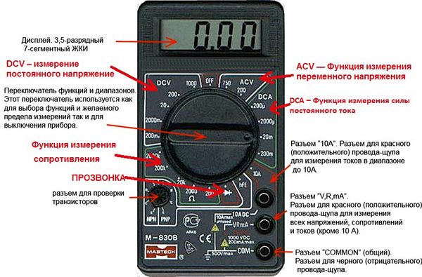
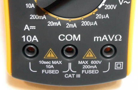
Perhaps you immediately noticed 3 connectors for connecting probes? So here you need to immediately warn you that it is necessary to correctly connect the tentacles to the tester before the measurements. The black wire is always connected to the output labeled COM. Red according to the situation: in order to check the voltage in the network, current strength up to 200 mA or resistance - it is necessary to use the “VΩmA” output, if you need to measure the current value above 200 mA, be sure to insert the red probe into the socket marked “10 ADC”. If you do not take this requirement into account and use the “VΩmA” connector to measure high currents, the multimeter will quickly fail because the fuse will burn!
There are also old-style instruments - analogue or, as they are commonly called, analogue multimeters. The model with the arrow is almost never used, because such a scale has a higher error, and besides, it is less convenient to measure voltage, resistance and current strength on an arrow display.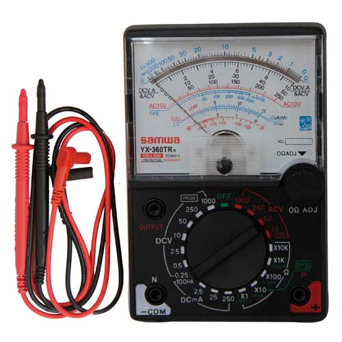
If you are interested in how to use a pointer multimeter at home, we immediately recommend watching a visual video lesson:
We will talk more about how to use the more modern digital model of the tester further, having examined the step-by-step instructions in the pictures.
Measure voltage
To independently measure the voltage in the circuit, you must first turn the switch to the desired position. In a network with alternating voltage (for example, in a socket), the switch arrow must be in the ACV position. The probes must be connected to the COM and “VΩmA” jacks. Next, select an approximate voltage range in the network. If at this stage there are difficulties, it is better to set the switch to the highest value - for example, 750 Volts.Further, if a lower voltage is displayed on the display, you can turn the switch to a lower level: 200 or 50 Volts. Thus, reducing the setting to a more suitable one, you can determine the most accurate value. In a constant voltage network, use a multimeter in the same way. Usually in the latter case, the switch is best set to around 20 volts (for example, when repairing car electricians).
A very important nuance that you should know about is that you connect the tentacles to the circuit in parallel, as shown in the picture: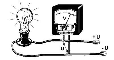
Here, by this technique, you need to use a multimeter to determine direct and alternating voltage in an electrical circuit. As you can see, there is nothing complicated, the main thing is not to touch the exposed parts of the tentacles with your hands, otherwise you will not be able to avoid electric shock. By the way, as a voltage indicator, you can also use indicator screwdriver!
Measure current
In order to independently measure the strength of the current in the circuit with a multimeter, it is first necessary to determine whether direct or alternating current flows through the wires. After that, you need to find out the approximate value in Amperes to select the appropriate socket for connecting the black probe - “VΩmA” or “10 A”. We recommend that you initially insert the probe into the connector with a higher current value and if a smaller value is displayed on the display, switch the plug to another socket. If, again, you see that the measured value is less than the setpoint, you must use a range with a smaller value in Amperes.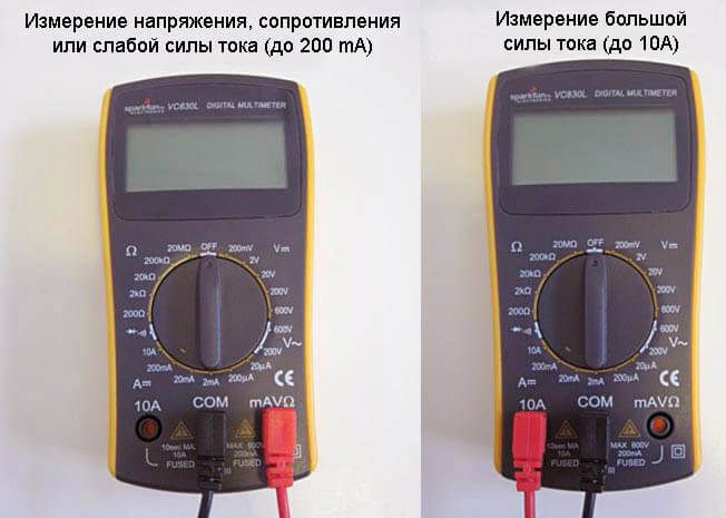
We draw your attention to the fact that if you decide to use the multimeter as an ammeter, you need to connect the tester to the circuit in series, as shown in the picture: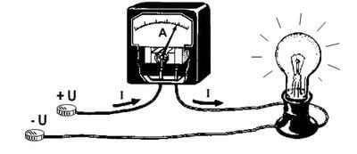
Measure resistance
Well and the safest thing in relation to the safety of the multimeter will use the device to measure the resistance of circuit elements. In this case, you can set the switch to any range of the "Ω" sector, and then select the appropriate setting for more accurate measurements. A very important point - before using the device to measure resistance, be sure to turn off the power in the circuit, even if it is a normal battery. Otherwise, your tester in ohmmeter mode may show an incorrect value.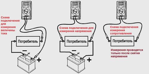
Most often, a multimeter measures resistance with repair of household appliances do it yourself. For example, if the iron does not work, you can measure the resistance of the heating element, which, most likely, has failed.
By the way, if when measuring resistance on a circuit section with a multimeter, you saw the value “1”, “OL” or “OVER” on the board, then you need to turn the switch to the range above, because at the selected setting, overload occurs. At the same time, if “0” is displayed on the dial, move the tester to a smaller measurement range. Remember this point and it will not be difficult to use a multimeter when measuring resistance!
We use the proverbial
If you look closely at the front panel of the tester, you can see some more additional functions that we have not yet talked about. Some of them use only experienced radio technicians, so there is no reason for a home electrician to talk about them (all the same, they are unlikely to be useful in living conditions). But there is another important tester mode that you may be using - dialing (in the picture below we indicated its designation). For example, to find zero wire break in the circuit, you need to ring the wiring, and if the circuit is closed, you will hear a sound indication. To do this, just connect the probes to the desired 2 points in the circuit.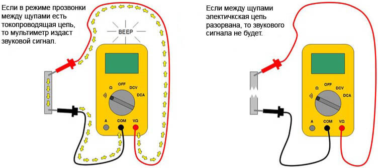
Again, a very important nuance is that the power on the part of the circuit that you are going to ring out must be disconnected. For example, if you decide ring wiring in the house, while operating, turn off the opening circuit breaker in the switchboard. Using the multimeter with the power connected is highly discouraged!
Related video tutorials
And finally, we advise you to see how to use the most popular multimeter models correctly. Perhaps you bought just one of the devices listed below and the visual instruction will show you how to use the purchased version of the meter!
This concludes our instruction. We hope that our material helped you learn how to use the basic modes of a universal device and now you know how to use the multimeter at home and what you need to measure resistance, voltage and current strength in a circuit!
We advise you to read:




Hello! I am a beginner, studying a multimeter and others. It is difficult, already retired for 6 years. I really liked your site. I will continue to use it with great pleasure. Nicely.
The article is very informative, but the author is very nasty!
It’s sacred to teach people, and to humiliate them by calling them a “teapot” is mean.
The teacher himself knows what I'm writing about.
I rummaged through the whole tyrnet, but did not find an explanatory explanation for using the dt182 multimeter.
Is it all the teapots in it, or is it just me?
Respect and respect to the author.
Next to the ringing, on the right, most likely the temperature, I have written “temp * C” on the device
In the paragraph "Measuring the current" error? [... to select the appropriate socket for connecting the BLACK probe ...] can it still be red, or is it not important for serial connection?
Accessible and intelligible ...
Many thanks ! Everything is clear and understandable.
Hello. I have a problem in the following. The chargers for the phone do not work in the house. Previously, everything was fine. The phones have to be charged from a laptop or from the receiver.
Please tell me what the problem may be?
Hello samovar! Tell me pliz how to measure the voltage of the battery, in series or in parallel, or in general how, a red probe to plus, and black to minus ???? in more detail and what will happen if, for example, in a Soviet car, measure the voltage, m832 with a multimeter, connecting it not in parallel, but in series ???? (I tried to measure the voltage that comes to the temperature sensor of the coolant ....... accordingly, the red probe “rested” on the wire that comes from the controller and the black “dropped” the mass ... .. Big Soviet Thank you, Dear Uncle Samovar, with experience in 5 ers old ....
And how do you connect the multimeter to the battery sequentially? Take the red probe to the plus, black to the minus. The voltage measurement mode should be enabled on the cartoon.
If you connect in series with the load, then the load will not work since the voltmeters have very high internal resistance. How did the voltage measurement on the DTOZH end?
They did everything right.
Read this article carefully. Everything is written well enough.
The first time I bought a multimeter. Your article and site are very good, but you don’t have the option to download instructions or (print, there’s no print anywhere from the site😁 we don’t pay attention), but the ability to download in pdf .pdf format would be nice. Thank you for your attention and adding a new feature. Send me a print version.Thank you very much.