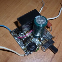
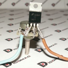
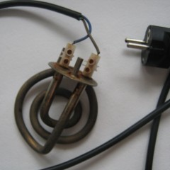
How to assemble a temperature controller at home
Bit of theory
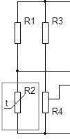
The simplest measuring sensors, including those that respond to temperature, consist of a measuring half-arm of two resistances, a supporting one and an element that changes its resistance depending on the temperature being adjusted to it. This is more clearly shown in the picture below.
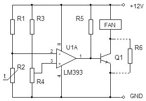
As can be seen from the diagram, the resistor R2 is a measuring element of a home-made thermostat, and R1, R3 and R4 are the supporting arm of the device. This is a thermistor. It is a conductor device that changes its resistance with temperature.
An element of the thermostat that responds to a change in the state of the measuring arm is an integrated amplifier in the comparator mode. This mode switches the output of the microcircuit from the off state to the operating position in a jump. Thus, at the output of the comparator, we have only two values “on” and “off”. The chip load is a PC fan. When the temperature reaches a certain value in the arm R1 and R2, a voltage shift occurs, the input of the microchip compares the value on pin 2 and 3 and the comparator switches. The fan cools the necessary object, its temperature drops, the resistance of the resistor changes and the comparator turns off the fan. Thus, the temperature is maintained at a predetermined level, and the operation of the fan is controlled.
Schema Overview
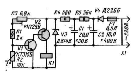
The voltage of the difference from the measuring arm is supplied to a paired transistor with a large gain, and an electromagnetic relay acts as a comparator. When the coil reaches a voltage sufficient to retract the core, it is triggered and connected through its contacts of the actuators. When the set temperature is reached, the signal on the transistors decreases, the voltage on the relay coil decreases simultaneously, and at some moment the contacts disengage and the payload is disconnected.
A feature of this type of relay is the presence hysteresis - this is a difference of several degrees between turning on and off a home-made temperature regulator, due to the presence of an electromechanical relay in the circuit. Thus, the temperature will always fluctuate several degrees near the desired value. The assembly option provided below is virtually devoid of hysteresis.
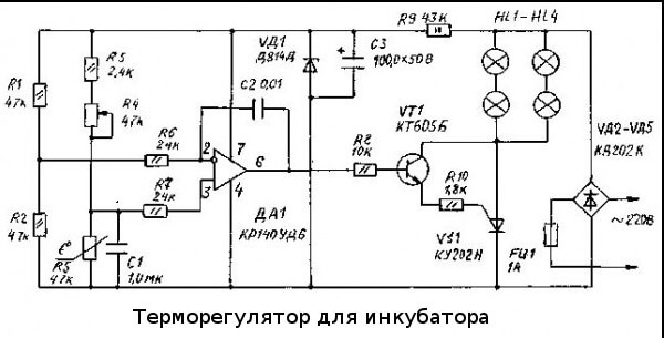
Schematic diagram of an analog temperature controller for an incubator:
This scheme was very popular for repetition in 2000, but even now it has not lost its relevance and can cope with the function assigned to it. If you have access to old parts, you can assemble a temperature controller with your own hands almost for free.
The heart of the homemade product is the K140UD7 or K140UD8 integrated amplifier. In this case, it is connected with positive feedback and is a comparator. The thermosensitive element R5 is a MMT-4 resistor with a negative TKE, which means that when heated, its resistance decreases.
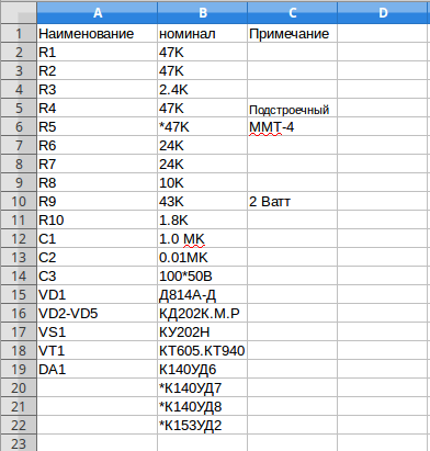
The remote sensor is connected via a shielded wire. For decreasing crosstalk and false operation of the device, the length of the wire should not exceed 1 meter. The load is controlled through the thyristor VS1 and the maximum allowable power of the connected heater depends on its rating. In this case, 150 watts, the electronic key - the thyristor must be installed on a small radiator, to remove heat. The table below shows the ratings of the radio elements for assembling the thermostat at home.
The device does not have galvanic isolation from the 220 V network, when setting up, be careful, there is a mains voltage on the elements of the regulator, which is dangerous to life. After assembly, be sure to isolate all contacts and place the device in a non-conductive housing. The video below discusses how to assemble a thermostat on transistors:
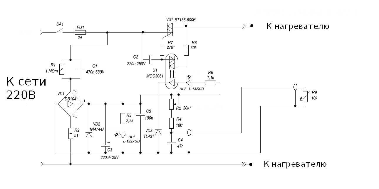
Now we will tell you how to make a temperature controller for a warm floor. The working diagram is copied from a serial sample. Useful for those who want to familiarize themselves and repeat, or as a model for troubleshooting the device.
The center of the circuit is the stabilizer chip, connected in an unusual way, the LM431 begins to pass current at a voltage above 2.5 Volts. This is the magnitude of this chip internal source of reference voltage. At a lower current value, it does not pass anything. This feature of it began to be used in various schemes of temperature regulators.
As you can see, the classic circuit with a measuring arm remains: R5, R4 - additional resistors voltage dividerand R9 is a thermistor. When the temperature changes, the voltage is shifted at the input 1 of the microcircuit, and if it reaches the threshold, then the voltage goes further according to the scheme. In this design, the load for the TL431 chip is the HL2 operation LED and the U1 optocoupler, for optical isolation of the power circuit from the control circuits.
As in the previous version, the device does not have a transformer, but receives power on the extinguishing capacitor circuit C1, R1 and R2, therefore it is also under a life-threatening voltage, and you must be extremely careful when working with the circuit. To stabilize the voltage and smooth out ripples of network surges, a Zener diode VD2 and a capacitor C3 are installed in the circuit. To visually indicate the presence of voltage on the device, LED HL1 is installed. The power control element is the VT136 triac with a small strapping for control through the optocoupler U1.
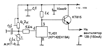
With these ratings, the control range is in the range of 30-50 ° C. With the seemingly seeming complexity, the design is easy to set up and easy to repeat. An illustrative diagram of the temperature controller on the TL431 chip, with an external power supply of 12 volts for use in home automation systems, is presented below:
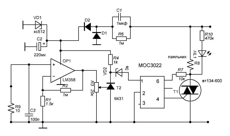
This thermostat is able to control a computer fan, power relay, light indicators, sound alarms. To control the temperature of the soldering iron there is an interesting circuit using the same TL431 integrated circuit.
To measure the temperature of the heating element, a bimetallic thermocouple is used, which can be borrowed from a remote meter in a multimeter or purchased at a specialized radio parts store.To increase the voltage from the thermocouple to the TL431 response level, an additional amplifier is installed on the LM351. Control is via the MOC3021 optocoupler and T1 triac.
When you turn on the thermostat in the network, it is necessary to observe the polarity, the minus of the regulator must be on the neutral wire, otherwise the phase voltage will appear on the soldering iron body, through the thermocouple wires. This is the main drawback of this circuit, because not everyone wants to constantly check the plug is plugged into the outlet, and if you neglect this, you can get an electric shock or damage the electronic components during soldering. Range adjustment is made by resistor R3. This scheme will ensure the long operation of the soldering iron, eliminate its overheating and increase the quality of the soldering due to the stability of the temperature regime.
Another idea of assembling a simple thermostat is discussed in the video:
We also recommend that you look at another idea of assembling a thermostat for a soldering iron:
Disassembled examples of temperature controllers are enough to meet the needs of a home master. Schemes do not contain scarce and expensive spare parts, are easy to repeat, and practically do not need to be configured. These homemade products can easily be adapted to regulate the temperature of the water in the tank of the water heater, monitor the heat in the incubator or greenhouse, and upgrade the iron or soldering iron. In addition, you can restore an old refrigerator by redoing the regulator to work with negative temperature values by replacing the resistances in the measuring arm. We hope our article was interesting, you found it useful for yourself and understood how to make a temperature regulator with your own hands at home! If you still have questions, feel free to ask them in the comments.
It will be interesting to read:

