5 assembly schemes for a homemade dimmer
Very often there is a need to control the brightness of the lamp within a certain value, this is usually from 20% to 100%. It does not make sense to set the brightness less, since most lamps simply do not work in this mode or give a tiny amount of light, which is enough only for the lamp to glow, but it will not illuminate anything. You can go to the store and buy a finished device, but now the prices for these devices are very high and do not correspond to the product received. Since we are handymen, we will do these devices on our own. Today we will consider several schemes, thanks to which it will become clear to you how to make a 12 V and 220 V dimmer yourself.
On the triac
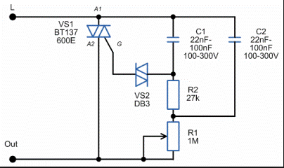
To begin with, consider the circuit of a dimmer operating from a 220 Volt network. This type of device works on the principle of phase displacement of opening the power switch. The heart of the dimmer is an RC chain. A node for the formation of a control pulse, which is a symmetric dinistor. And actually, the power switch itself, which controls the load, is a triac.
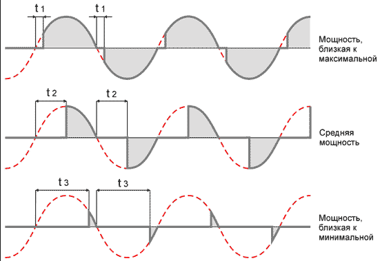
Consider the operation of the circuit. Resistors R1 and R2 form voltage divider. Since R1 is variable, with its help the voltage in the R2C1 chain changes. The DB3 dinistor is connected to the point between them, and when the voltage of the threshold of its opening on the capacitor C1 is reached, it is triggered and gives a pulse to the power switch - the triac VS1. It opens and passes current through itself, thereby we get voltage at the output. What part of the wave goes to the lamp depends on the position of the regulator. The faster it charges capacitor, the faster the key opens, and most of the wave and power will go to the load. Thus, the circuit literally cuts off part of the sinusoid. Below is a graph of the device.
The value (t *) is the time during which the capacitor is charged to the opening threshold of the power element. This dimmer circuit is simple and easy to repeat in practice. It works best on incandescent lamps, because the spiral in the lamp has an inertia, but there can be problems with LED and other lamps, so it is necessary to check the operation of the circuit specifically for your consumers before the final installation. We recommend watching the video below, which clearly shows how to make a dimmer on the triac:
On thyristors
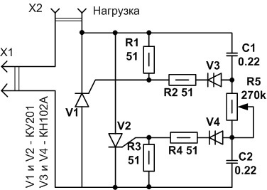
You can not buy a triac, but make a simple dimmer on thyristors, which can be easily removed from old idle equipment and circuit boards, like televisions, tape recorders, etc. The scheme is slightly different from the previous one, in that each half-wave has its own thyristor, and thus its own dynistor for each key.
We briefly describe the regulatory process. During the positive half-wave, the capacitance C1 is charged through the chain R5, R4, R3.When the threshold for opening the dynistor V3 is reached, the current through it enters the control electrode of the thyristor V1. The key opens, passing a positive half-wave through itself. In the negative phase, the thyristor is locked, and the process is repeated for another key V2 and capacitor C2, which is charged through the chain R1, R2, R5.
Phase controllers - dimers can be used not only to adjust the brightness of incandescent lamps, but also to regulate the speed of the exhaust fan, you can make a prefix for the soldering iron and thus adjust the temperature of its tip to improve the quality of soldering.
Video assembly instructions:
Important!This control method is not suitable for working with fluorescent, economical compact and LED lamps due to the peculiarities of their operation.
Condenser dimmer
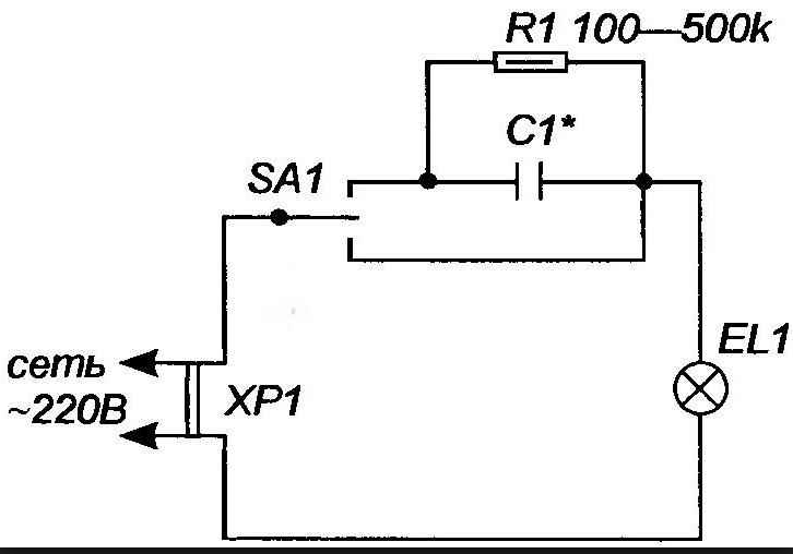
Along with smooth regulators, capacitor dimmers have become widespread in everyday life. The operation of this device is based on the dependence of AC transmission on the value of capacitance. The larger the capacitor, the more current it passes through itself. Thus, using a capacitor, you can reduce the power supplied to the lamp, however, this method does not allow for smooth adjustment. This type of homemade dimmer can be quite compact, it all depends on the required brightness parameters, and therefore on the capacitance of the capacitor, which is associated with its size.
As you can see from the diagram, there are three positions: 100% power, through the quenching capacitor (power reduction) and off. The device uses a non-polar paper capacitor, which can be obtained in the old technique. About, how to solder radio components from boards we told in the corresponding article!
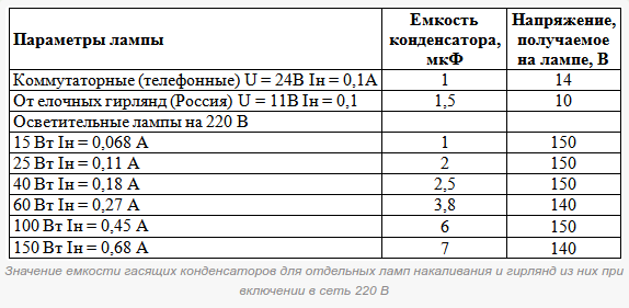
Below is a table linking the capacitance and voltage on the lamp.
Based on this scheme, you can build a simple nightlight yourself and use the toggle switch or switch to control the brightness of the lamp.
On the chip
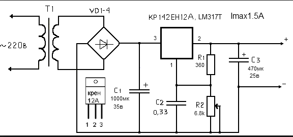
To regulate the power supplied to the load in direct current circuits of 12 volts, integral stabilizers are often used - Krenki. The use of microcircuit simplifies the development and installation of devices due to the small number of radio components. Such a homemade dimmer is easy to configure and has some protection features.
Using a variable resistor R2, a reference voltage is created on the control electrode of the microcircuit. Depending on the parameter set, the output value is adjusted from a maximum of 12 V to a minimum of tenths of a Volt. The disadvantage of these regulators in low efficiency and the maximum possible power of the connected load, as a result of this, there is a need to install an additional radiator for good cooling of the ROLL, since part of the energy is released on it in the form of heat. However, it is ideal for low power DC and low voltage circuits, due to its simplicity and versatility.
This dimmer was repeated by me and did an excellent job with a 12-volt LED strip, three meters long, and made it possible to adjust the brightness of the LEDs from zero to maximum.
An excellent option is a dimmer on the 555 integrated timer, which controls the KT819G power switch, short PWM pulses. By setting a high frequency of the circuit, you can get rid of the flicker, which often occurs due to cheap purchased dimmers and causes rapid fatigue and eye irritation in humans.
In this mode, the transistor is in two states: fully open or completely closed. The voltage drop across it is minimal, which allows you to connect a more powerful load and use a circuit with a small radiator, which compares favorably with the dimensions and efficiency compared to the previous circuit with a regulator on the ROLL.
Finally, we recommend that you look at another master class, which shows how you can make a dimmer for LEDs:
That's actually all the ideas for assembling a simple dimmer at home. Now you know how to make a dimmer with your own hands on 220 and 12V.
It will be interesting to read:

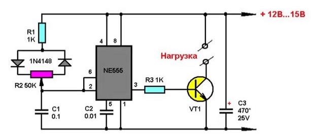




In the circuit with the timer ne555 error. pin 7 is not connected anywhere.
Because of this, the circuit does not work.