How to check the operation of the circuit breaker?
Briefly about circuit breakers
Circuit breakers are designed to act as switching devices necessary for carrying a load current in normal operation of the equipment and opening the electrical circuit in emergency mode at high or low voltage.
AVs have been widely used due to the simplicity of installation, reliability in operation, safety during replacement and maintenance, quick response at short-circuit currents or abnormal conditions. Such machines are installed in electrical installations with both low and high power.
There are devices with manual and remote control. In abnormal conditions, the switch trips automatically. All devices are equipped with an overcurrent release. Some models are equipped, in addition to the maximum and with a trip on the minimum current. Such machines are designed to replace circuit breakers or fuses in cork fuses, which provides more reliable protection for household appliances and connected equipment.
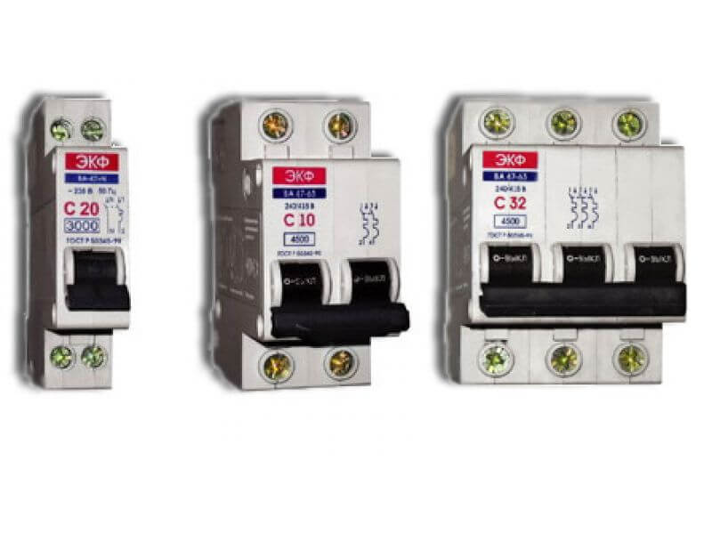
AB are produced mainly for amps from 6.3A to 6300A for AC installations up to 1 kV, with a different number of poles. It can be single, double, triple and four-pole circuit breakers.
More on circuit breaker device You can find out in our corresponding article. Now I would like to additionally tell only that protection against abnormal conditions is provided by an electromagnetic release, due to which the device is switched off.
There are two types of releases:
- electromagnetic or maximum release from short-circuit currents and overload (without time delay);
- thermal (electronic), triggered at currents significantly exceeding the rated values of the load currents (with time delay).
Both types of protection must comply with the regulatory documents of the manufacturer (PTEEP in Appendix 3). In order for the device to work properly before installation of a circuit breaker it must be checked. This operation is called loading the machine, which we now dwell on in more detail.
Loading Technique
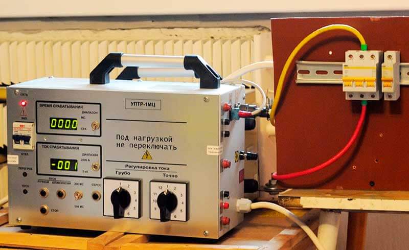
During loading, the main characteristics of the machines (rated current, protection operation current, protection operation time under abnormal conditions) are measured on a special installation.All work on checking the performance is carried out by special personnel who have access to such tests, with a certificate with a mark on admission to special works on testing electrical equipment.
The certificate must indicate the safety group, and the voltage at which the employee can conduct checks (up to or above 1000V). The certificate must be signed by the chief power engineer of the enterprise that conducts the verification work. The AB loading procedure in the factory must comply with GOST for low-voltage control and distribution equipment.
Equipment
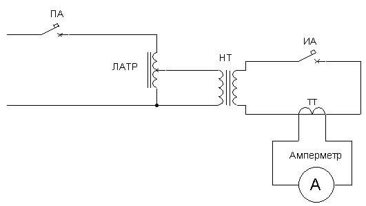
In order to check (load) the circuit breaker, you need to assemble a fairly simple circuit that includes the necessary equipment for testing:
- connecting wires;
- KU - control key;
- LATR - laboratory autotransformer, for changing the load;
load transformer or load transformer (NT); - ammeter as a shunt;
- TT - current transformer.
The scheme of the device for checking AB:
The method of loading requires partial dismantling of the apparatus, after checking the serviceability - reverse installation.The device for testing may be of a different type, the main thing is that an artificial short circuit current is supplied to the AB with the measurement of its value, and taking into account the response time of the protection of the machine in the electrical network.
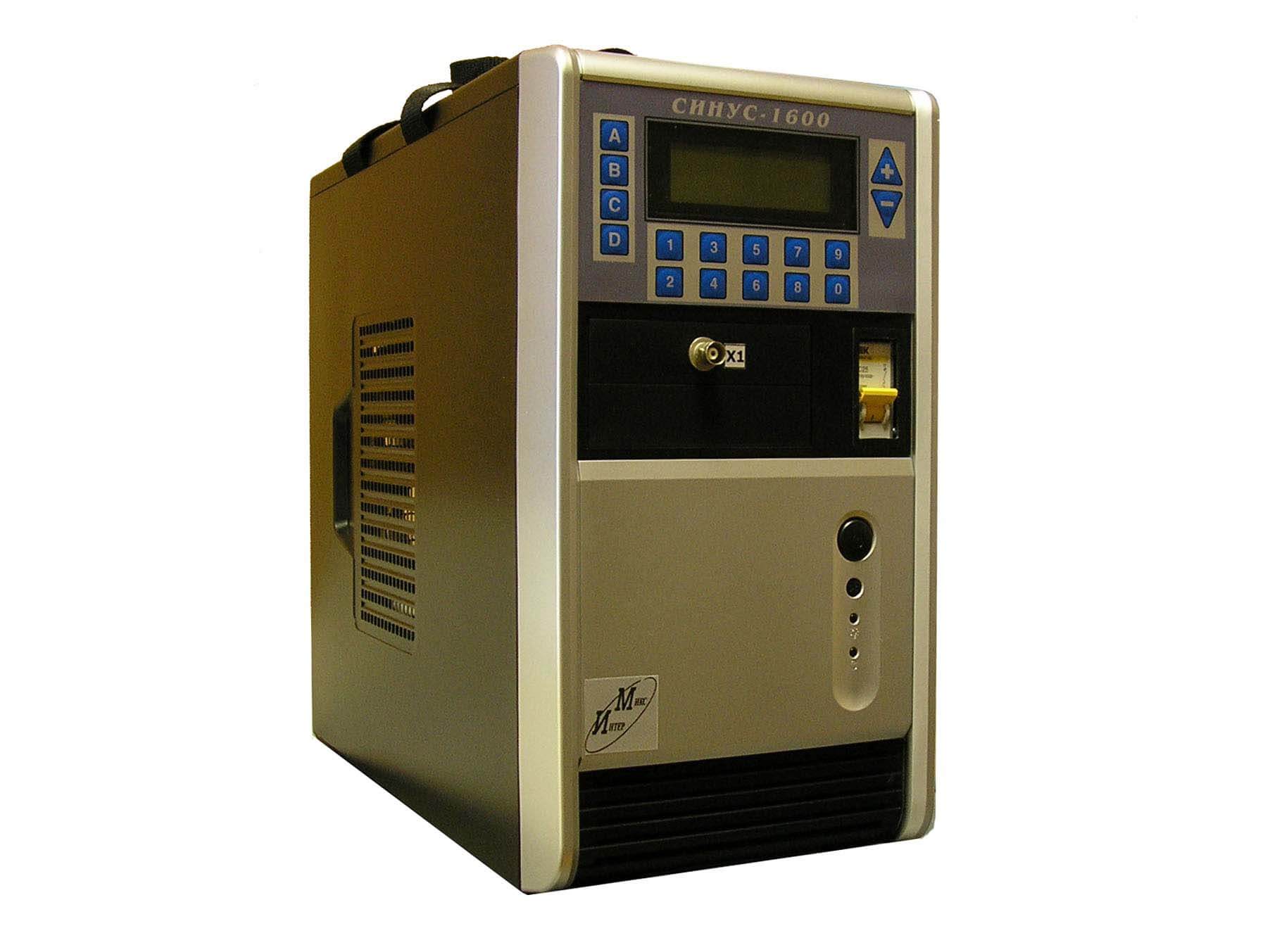
There are even special kits for checking the AB, for example, SINUS-1600, shown in the photo:
The process itself
The circuit breaker is loaded with an electromagnetic release to determine the time automatic operation within the protected zone according to the factory characteristics. To do this, the load current is set on the test device, which is equal to the maximum amperage for this type of AB and time, according to the factory characteristics.
To test the thermal release, a triple load current and a maximum tripping time, which is in accordance with the factory characteristics, are set at the test installation. Usually this time is from 5 seconds. up to 0.5min.
In detail, all actions to check the machine are discussed in the video:
All the results of the work are recorded in the protocol. The document reflects the magnitude of the induced amperage and the response time of the machine. The loading protocol is signed by the person conducting the test. A sample verification protocol is provided below:
Test Dates
The frequency of testing should be specified in the accompanying regulatory documents of the manufacturer, but the recommended check is every three years during normal operation of the circuit breaker at the rated load current. In case of emergency interventions or abnormal operation of the AB, the frequency can be changed, and an unscheduled check should be carried out. All recommendations apply to household appliances and circuit breakers installed in production facilities.
According to the PUE ch. 3.2, clause 1.8.37 loading of circuit breakers on input and sectional protection devices, emergency lighting networks, fire alarms - 2% of AV group networks. PUE requirements for other electrical installations 1% of all installed machines.
In the event of detection of circuit breakers that do not correspond to the factory specifications, the procedure for checking the entire batch is carried out. After loading, a stamp must be placed on each device with the logo of the laboratory conducting the test, the date of the test and the word “Tested” or “Expired until ... (date)”. This indicates that the machine has passed the test and is suitable for operation.
Here, according to this technique, the circuit breakers are tested with a voltage of up to 1000 V. As you can see, you can even load a circuit breaker with a device assembled at home, the main thing is to know the safety precautions and test technology.We hope that now you know what and how to do to independently check the disconnecting ability of the protection device.
It will be interesting to read:




Good afternoon. Help me to understand. I wanted to reduce the load on the network. To do this, we decided to include m-NT12 in the network with Saturn
When connecting terminal 1 (NT-12) to terminal 3 "Saturn" short circuit occurs. Everything is assembled according to the scheme. Tell me please what could be the problem.
Hello! Send the scheme according to which the test bench was assembled. Check again the correct installation made by you.
Good afternoon, please help fill out the table. Circuit Breaker type IEK BA 47-29 C25 and second AB Schn Elec In 400A Ir = 0,8xIn. The time response range is in the passport, i.e. I need 3,4,5,7 columns in the table. Thank!
Tell me, is it necessary to load automatic machines, if they were purchased and installed for the first time? And is there any NTD where it is written?
In your automatic loading protocol, the response time range is 7-23 sec. Where did these numbers come from? Tell me please. And then the customer asks this question, but I can not answer. PUE refers to the factory passport. I looked through several passports, even close there is nothing like it.