Break relay based on the widespread “breaker”
Description of development
All this is a significant drawback of this thermal release. Looking ahead, it must be said that the organization of remote control of these contacts allows you to replace the bimetal plate with a conventional one, and current control is carried out using an electronic sensor and the corresponding key circuit. The result is a fully functional release with good performance. But, this is in the future, and now we will consider a model designed for voltage protection devices. The current protection indicators in it remain the same as in the original breaker.
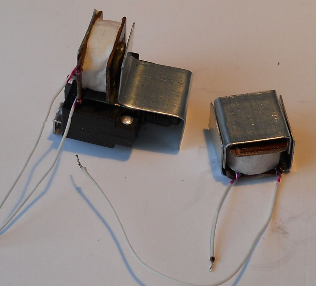
For testing and presentation of two experimental modifications of the break relay, two surge protection devices were manufactured on the basis of a VI-TOK 3-socket splitter, without a synchronous limiter. The photo below shows a complete set of break relays before final assembly. As will be shown below, the relay is relevant and without automatic control of the reset, that is, with one electromagnet.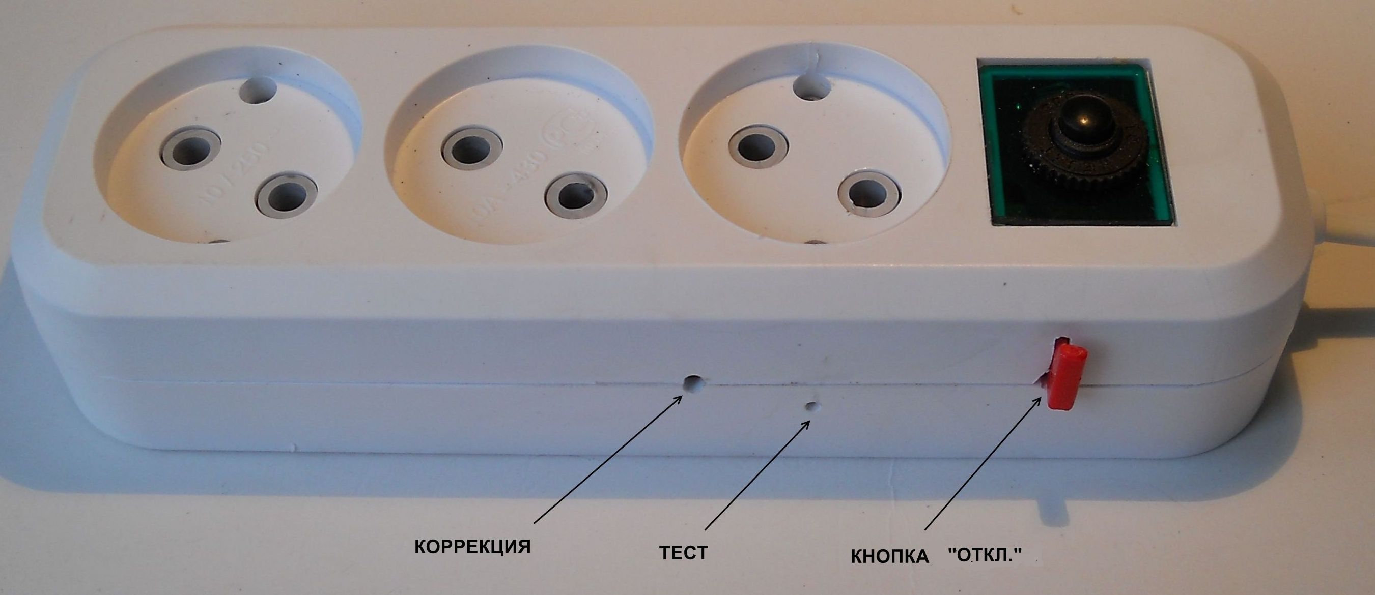
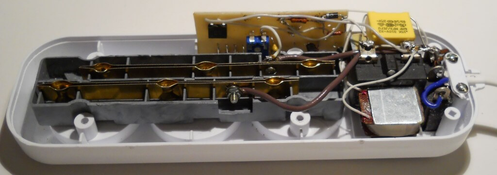
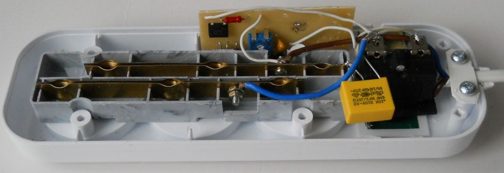
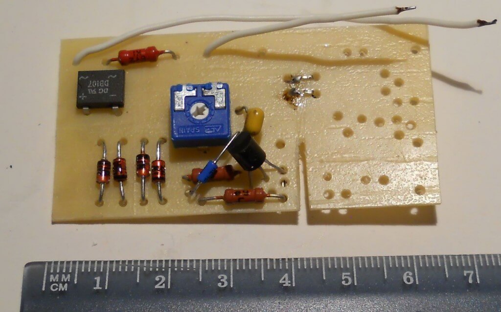
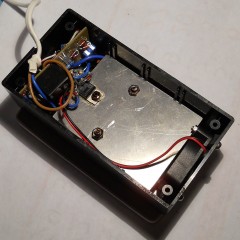
Miniature electromagnets have the most economical (cost) design. The magnetic cores are made of a soft galvanized strip of 20x0.75 mm (a tare strip is also suitable), the cores are made of d5 (d6) wire, the coil winding is made with a 0.1 mm wire. It has already been noted that the circuit of a protective device with a break relay is the most simple and reliable. It does not contain a single element of increased power and not a single electrolytic capacitor, that is, it has the largest resource.In standby mode, the consumption is 0.5 - 0.8 watts. Below are photos of the internal installation of protection devices with auto return and without auto return, and the board of the second of them, which demonstrate structural simplicity well.
It was previously noted that automatic return to the initial standby state is necessary mainly for refrigerators. Here I must say that it is useful for computer equipment connected to an uninterruptible power supply (for this kit), and for other equipment, for example, for video surveillance systems. At the same time, auto-return for TVs and other audio-video equipment is not necessary at all. Thus, two break-relay models and, accordingly, the following models of protection devices are considered relevant:
- A model of a filter splitter with a power cut-off and manual reset, and a similar model, but with automatic return.
- Synchronous limiter (ONS) with auto-cut and manual return, and with automatic return.
The models according to claim 1, as well as the filters now produced, are suitable only for stable urban networks. It should be noted that such a model, but with a break relay, is most economical. It may not have an input switch either, since it is structurally simple to install a button for the break relay electromagnet, either electric or mechanical. Auto return in the presented design does not exclude manual return - it becomes a backup.
Here it should be noted one more positive difference between protection devices based on break relays from existing ones that use a conventional relay as a release. The protection device must be designed for an input emergency voltage of up to 380 volts, since the likelihood of such an accident in the power supply network is low, but it always takes place, and its destructive effect is very high, the cost of losses is high. So, relay protection, or rather the circuit of this protection in existing devices, is usually not designed for such a voltage (since costs increase significantly). Manufacturers do not give any guarantees in this case.
The difference between the break relay is that it instantly, in 2 - 3 ms, turns off everything, that is, it works like a current automaton. As for the scheme for providing auto-return, it must be said that its elements operate at currents of less than 2 - 3 mA and have a sufficient voltage margin. That is, in contrast to the relay circuit, the heat dissipation on the elements is significantly less. The excess voltage in the input voltage control circuit is distinguished by means of the classical current limiting circuit using a high-voltage low-power transistor, shunted by a resistor of the order of 100 kOhm.
It should be noted that a neon indicator is used in the auto-return scheme, which, in addition to the main function, is useful in that it allows documenting (with an act with witnesses) the fact of the prolonged presence of an unacceptably high voltage in the network (to compensate for damage to unprotected power supply areas, including among neighbors, through the court). Here it is necessary to draw the attention of readers to the fact that the issue of compensation for damage from high voltage in the network (due to the high price of modern equipment and especially its repair) should be comprehended and studied by each consumer in advance.
According to our information, the legal side of this, one can say, problem requires serious work of the relevant departments. But, whatever the legal decisions, technical protection devices should ensure that the fact of unacceptable overvoltage in the network is recorded, and the legal fixing of this fact should be carried out by the expert technical service. Obviously, service centers for warranty service and repair of protection devices can also do this.Many modern devices have a digital voltage indicator, but in this case, an expert opinion is required on the accuracy of the measurement and on the serviceability of the protective device, that is, technical confirmation of the fact of overvoltage. This topic is relevant and it will be useful to consider it separately. Here it remains to complete the story of a new development - a break relay.
As before, in the order of advice to the masters, it must be said that the cut-off duration indicated above was measured during tests by means of an RC circuit connected to this electromagnet for this purpose. By measuring the voltage across the capacitor after the cutoff pulse and knowing the constant of the charge time, as well as the fact that the actuation occurs in the region of the half-wave peak, we can calculate the approximate cutoff pulse duration, that is, the time from the opening of the thyristor to the blackout.
Break relay test
Those who want to see the tests of the presented models can download these files:
You need to watch them with sound of a normal level. When testing the break relay, I used a conventional transformer recommended by me earlier with voltage boost windings and with a voltage regulator resistor. The resistor is shunted with a triac key to provide a current pulse of the cutoff and return electromagnets (about 6 A). The push-button cut-off test is the same as in the synchronous limiter. The shutter speed is counted down after the voltage drops below the cutoff point and is a few seconds. A longer shutter speed requires the use of an electrolytic capacitor, which is not a reliable element, and a shutter speed of more than half an hour (for a refrigerator) also complicates the circuit.
In this regard, it should be noted that it is real - without any protection devices, the power supply is always likely to disappear for a few seconds or less (for example, due to poor contact or from accidentally turning off the general circuit breaker). Therefore, all equipment should be designed by manufacturers for such a power interruption. A longer delay is required only for special equipment, for example, for some refrigerators. Then you need to connect them through a special time relay, which, by the way, should be supplied by the Manufacturers themselves (than to shift this to consumers, force them to purchase special protection devices). But, this is from an engineering point of view. And from the point of view of the Consumer, not limited in means, there should, of course, be the opportunity to purchase a model of a protective device with a wide range of time delay, up to and including auto-shutdown. This is implemented, by the way, in many types of stabilizers, - with the corresponding cost and a number of shortcomings, which were mentioned earlier.

