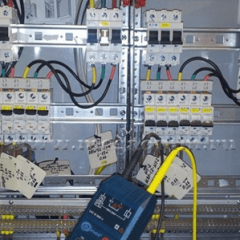
How to measure phase-zero loop resistance?
Frequency and purpose of measurements
For reliable operation of the power supply network, it is necessary to periodically check the power cable and equipment. Before putting the facility into operation, after overhaul and current repair of the power supply network, after commissioning, as well as on the schedule established by the head of the enterprise, these tests are carried out. Measurements are made according to the following main parameters:
- insulation resistance;
- loop resistance phase zero;
- grounding parameters;
- parameters of circuit breakers.
The main task of measuring the phase-zero loop parameter is to protect electrical equipment and cables from overloadsarising during operation. Increased resistance can lead to overheating of the line, and as a result, to a fire. The environment has a great influence on the quality of the cable and overhead line. Temperature, humidity, aggressive environment, time of day - all this affects the state of the network.
The circuit for measurements includes automatic protection contacts, circuit breakers, contactors, as well as conductors for supplying voltage to electrical installations. These conductors can be power cables supplying phase and zero, or overhead lines that perform the same function. In the presence of protective grounding - phase conductor and grounding wire. Such a circuit has a certain resistance.
The impedance of the phase-zero loop can be calculated using formulas that take into account the cross section of the conductors, their material, the length of the line, although the accuracy of the calculations will be small. A more accurate result can be obtained by measuring the physical circuit with existing devices.
In the case of using a residual current circuit breaker (RCD), it must be turned off during measurement. The RCD parameters are designed so that when large currents pass, it will turn off the network, which will not give reliable results.
Methods Overview
There are different methods for checking the phase-zero loop, as well as a variety of special measuring instruments. As for measurement methods, the main ones are:
- Voltage drop method. Measurements are carried out with the load off, after which the load resistance of a known value is connected. Work is performed using a special device. The result is processed and using the calculations make a comparison with regulatory data.
- Short circuit method. In this case, connect the device to the circuit and artificially create a short circuit at the far point of consumption. Using the device, the short circuit current and the response time of the protections are determined, after which they conclude that they comply with the norms of this network.
- Ammeter-voltmeter method. They remove the supply voltage and then, using a step-down transformer on alternating current, close the phase wire to the housing of the existing electrical installation. The data obtained are processed and using the formulas determine the desired parameter.
The main methodology for this test was to measure the voltage drop when connecting a load resistance. This method has become the main one, due to its ease of use and the possibility of further calculations that need to be carried out to obtain further results. When measuring the phase-zero loop within the same building, the load resistance is switched on at the farthest section of the circuit, as far as possible from the power supply. Connecting devices is carried out to well-cleaned contacts, which is necessary for the reliability of measurements.
First, the voltage is measured without load, after connecting the ammeter with the load, the measurements are repeated. According to the data obtained, the phase-zero circuit resistance is calculated. Using a ready-made device designed for such work, you can immediately get the desired resistance on a scale.
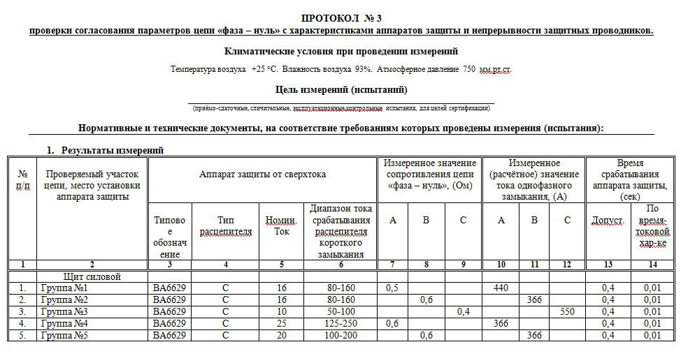
After the measurement, a protocol is drawn up in which all the necessary values are entered. The protocol should be in standard form. It also includes data on the measuring devices that were used. At the end of the protocol, they summarize the compliance (non-compliance) of this section with the regulatory and technical documentation. A sample protocol is as follows:
What devices do they use?
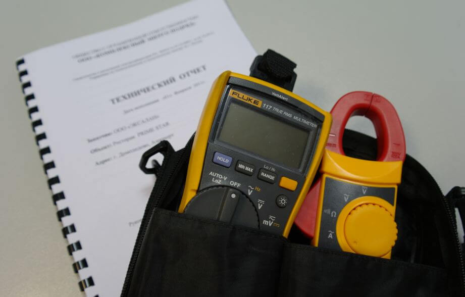
To speed up the loop measurement process, the industry produces a variety of measuring instruments that can be used to measure network parameters using various methods. The following models gained the most popularity:
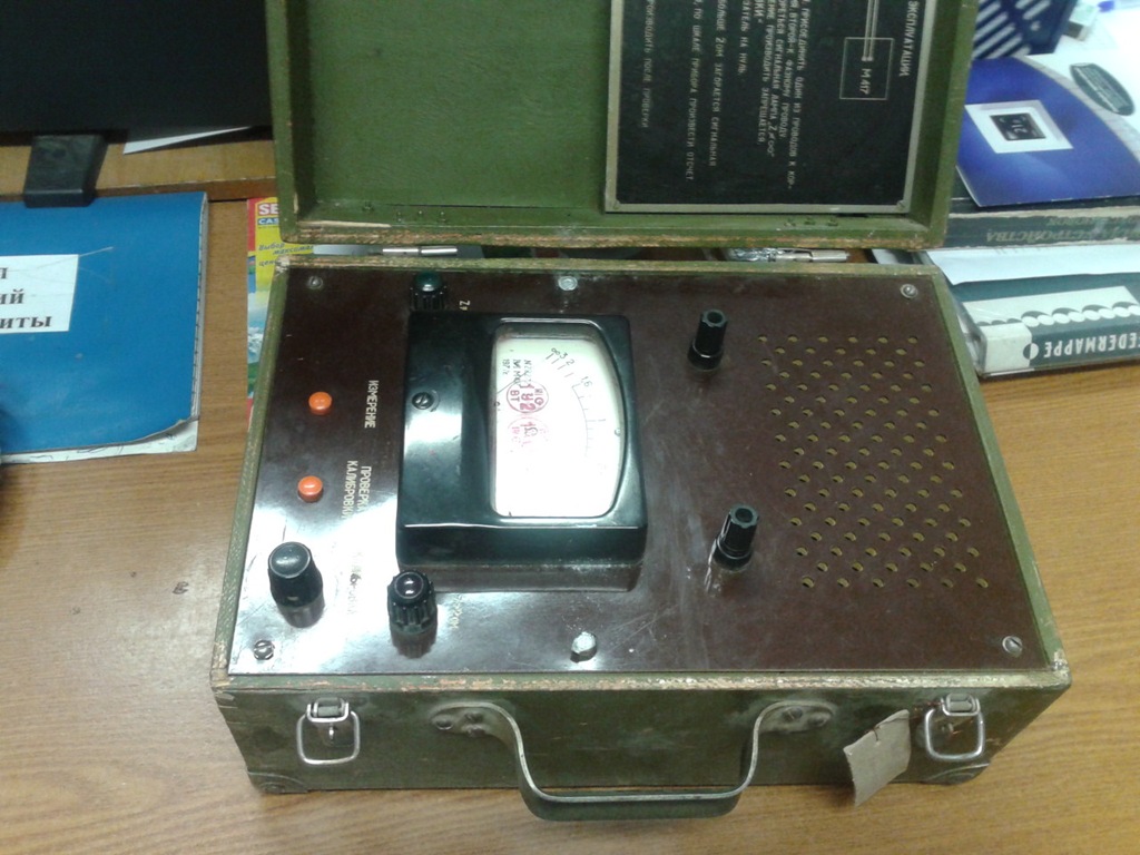
- M-417. Proven over the years and reliable instrument for measuring the resistance of a phase-zero circuit without removing power. Used for measuring the parameter by the method of voltage drop. When using this device, it is possible to test a circuit with a voltage of 380 V with a grounded neutral. It will provide an open circuit in 0.3 s. The disadvantage is the need for calibration before starting work.
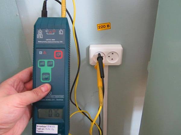
- MZC-300. A new generation device based on a microprocessor. It uses the method of measuring voltage drop when connecting a known resistance (10 ohms). Voltage 180-250 V, measuring time 0.03 s. Connect the device to the network at a distant point, press the start button. The result is displayed on a digital display, calculated using the processor.
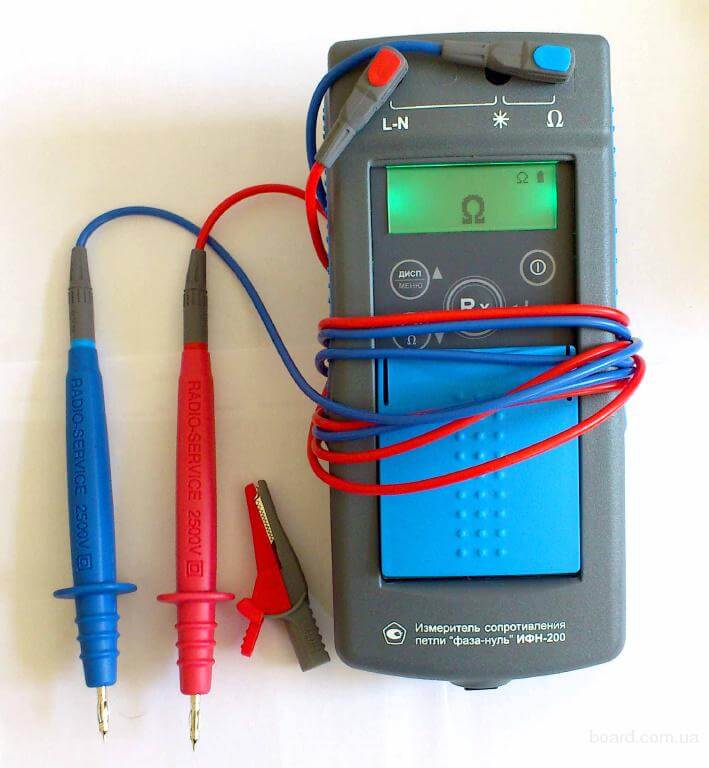
- IFN-200 measuring instrument. It performs many functions, including phase-zero loop measurement. The voltage is 180-250 V. There are corresponding connectors for connecting to the network. Ready to work in 10 s. The connected resistance is 10 ohms. If the circuit resistance is more than 1 kOhm, the measurements will not be carried out - the protection will work. Non-volatile memory saves 35 last calculations.
You can find out how to measure the resistance of a phase-zero loop using instruments by watching these video examples:
To use the above methods, only trained personnel should be involved. Incorrect measurements can lead to incorrect final data or to failure of the existing power supply system.Worst of all - this can result in personal injury. We hope that now you know what the phase-zero loop measurement is for, and also what methods and instruments can be used for this.
We also recommend reading:

