What is the UZM-51M for and how to connect it?
Device features
The main functionality of the UZM-51M:
- two-level protection against overvoltage, with delayed shutdown;
- two-level system of protection against undervoltage, with a delay on shutdown;
- semiconductor, varistor damping system for surge surges;
- the ability to remotely control ultrasound, enable and disable;
- wide range of thresholds.
By the way, the RN-106 relay (Novatek) is a close analog of the protection device UZM-51.
Appointment
Many are interested in what UZM-51M is for. This device is designed to disconnect and protect electrical devices when the mains voltage exceeds the specified limits. It is used to protect against neutral breakage in household networks, as well as from the harmful effects of high voltage surges that occur during operation of electric motors, magnetic starters, and other powerful devices. It absorbs impulses in an internal chain.
You can clearly see what UZM-51M is used for in this video:
The multifunction protection device cannot protect against short circuit and leakage currentsTherefore, it is necessary to take measures and install additional circuit breakers and RCDs!
Appearance and design
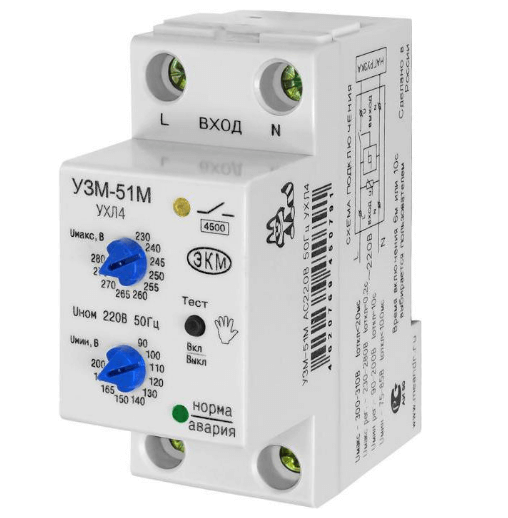
You can see how the UZM-51M looks in the photo below:
As for the design of the device, the multifunction protection device is a voltage monitoring relayhaving a powerful electromagnetic relay at the output, which is additionally equipped with varistor protection. The terminals have a tunnel design, which makes it possible to clamp wires with a cross section of not more than 35 mm2. The front side of the USM is equipped with two indicators. The first signals the status of "Norm" and "Alarm", respectively, green and red. The second, yellow, signals the inclusion of relay contacts. In addition, on the front side there is a “Test” button, designed for manual control of the device (you can turn on the load yourself). Also, like a voltage relay, the UZM-51M has regulators for the upper and lower protection thresholds.
main parameters
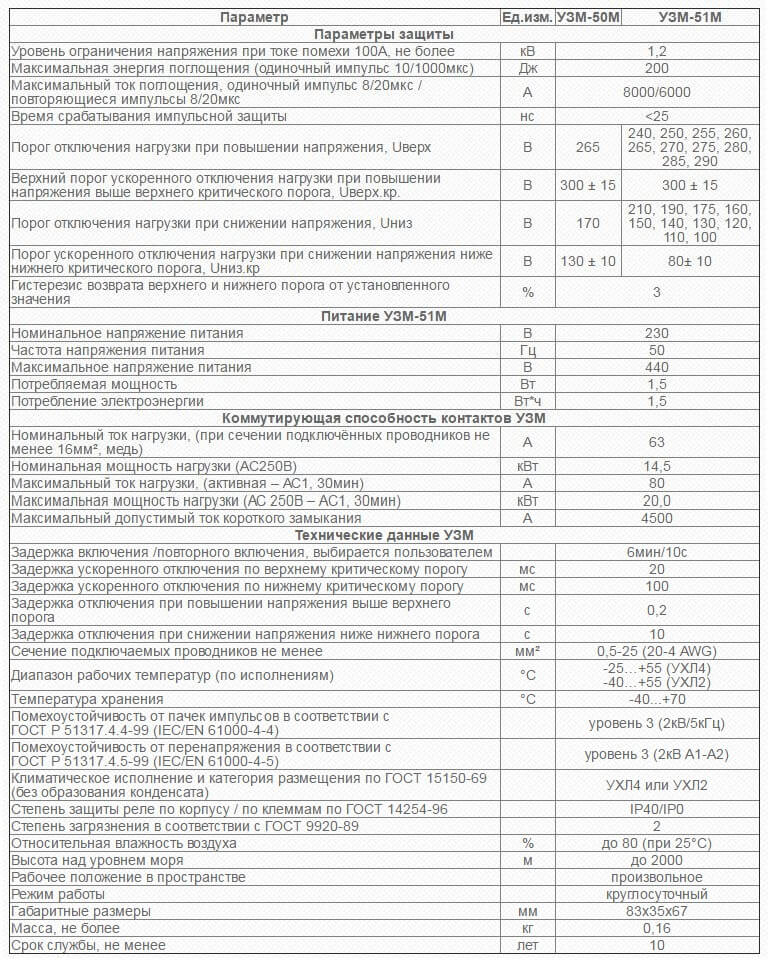
Technical characteristics of UZM-51M (rated and maximum current, operation thresholds, etc.) are summarized in the table below:
Principle of operation
It is also important to explain how the UZM-51M works. After turning on the device in the network, there is a time delay before turning on, at this moment the input voltage is measured.If the voltage is within acceptable limits, the green indicator turns on - the device is ready for operation, power is supplied to consumers. Otherwise, the yellow indicator lights up and the load does not connect to the network.
If during operation of the ultrasound scanner the voltage approached the upper threshold, the yellow LED starts to flicker, and when it goes beyond it, the load is turned off, the red light lights up. This signals an excess of the set parameters. In the case when the voltage drops to the lower threshold, the green LED starts to flicker, and when you go beyond the set limits, the red indicator lights up and flickers.
When you press the Test button on the device’s case, the red and green LEDs alternately switch, and the load is disconnected from the network. To return to working condition, it is necessary to press the “Test” button again.
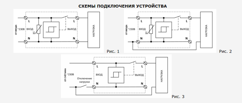
Wiring diagram
In the first figure, four is a wired connection diagram. Above is the input of the network wire, from below is the output to consumers. In the second figure, a three-wire circuit, where the phase wire enters and leaves the device, and zero is used to power the ultrasound circuit. In the third - a remote control circuit of the ultrasound scanner, zero feeds the device through a switch, and the phase is switched by the device, supplying voltage to the load.
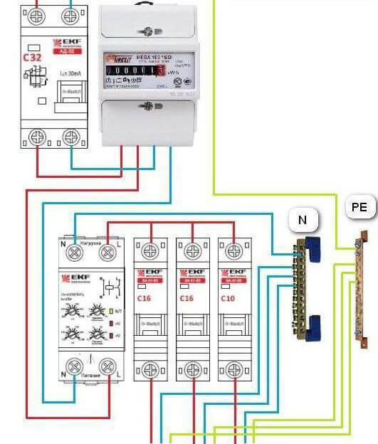
We also recommend that you look at the diagram how to connect an ultrasound scanner to a single-phase network of an apartment or house:
So we examined the features of the connection, device and purpose of the UZM-51M. We hope the information provided was useful and interesting for you!
We also recommend reading:



Duck will save or not, this device, if suddenly phase b goes to zero, when the device itself is powered from phase a?
It will save if you get 400 volts in the network and the TV dies for 700,000
link to the tv in the studio
It saves only from power surges in both directions, and in order to protect yourself from other factors you put after this device not simple machines, but diff or ouzo then you can not worry about the technique)
The other phase is zero - this will be a voltage surge of up to 380 V.
The same phase with zero instruments will not harm at all, because the potential difference disappears - they simply turn off.
UZM - device protection device.
RCD / difavtomat - a human protection device.
Alternating current. There is no “+" or "-" and your device doesn’t care where the phase is, and where it is zero. But when you turn on the TV in the socket, you have no idea which side the phase is on in the socket, and where is zero.
And this, as it were, Physics 8th grade ..
And it will save you from the extra money in your pocket.
What does the indication mean when both lamps are yellow and the relay does not respond to the on / on button?
Probably, the UMM is malfunctioning, since the Norm / Alarm indicator can glow either green or red, and it will turn yellow only if it glows green and red at the same time, which should not be in a good USM.
Tell me, there was a 51m month 2 months; everything was fine, but then suddenly I heard a click as if the machine had knocked out and the whole unit didn’t turn on anymore, there is no indication, there is no voltage at the output, it came to an end suddenly or something else may be worth it under warranty or a dead number?