What is grounding and what is it for?
Operating principle
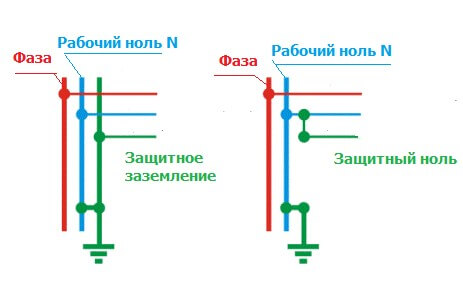
The work of protective grounding and protective grounding is different in that when grounding, if dangerous potential appears on the equipment case, it can happen short circuit. Under the action of a short circuit current several times larger in value than the rated current of the network, a fuse or other protective device is activated. With protective grounding, the damaging effect of the electric current is neutralized by reducing the value of the touch voltage (and step voltage) to a safe value. Damaged household appliances or electrical equipment that do not have protective grounding or grounding can be energized for a long time and become dangerous to humans at the moment of contact or when approaching the equipment at a dangerous distance.
As mentioned above, when a phase gets on the device body, which is made of metal and connected to the protective conductor, a short circuit occurs. The magnitude of the short circuit current is several times greater than the nominal current. Under its influence, protection devices are triggered. As a result, the electrical lines connected through the protective device are disconnected.
The cross-sectional area of the conductors should be selected based on the requirements of the relevant chapters PUE. For protective conductors PUE (section 1.7.5) determines the dependence of their cross section on the phase conductor cross section. So for cross-sectional areas of phase conductors less than 16 mm2, the size of the cross-sectional area of the protective conductor is equal to the cross-sectional area of the protective conductor. If the cross-sectional area of the phase conductor is in the range from 16 to 35 mm2, then the cross-sectional area of the protective conductor is 16 mm2 and if the cross-sectional area of the phase conductor is greater than 35 mm2, then the area of the protective conductor is chosen 2 times less. Also, the cross-sectional area can be calculated independently on the basis of the same item of the PUE. The main condition for choosing is to ensure speed, which is calculated by the formula:
S≥ I * √t / k,
This formula reflects the direct dependence of the value of the cross-sectional area of the protective conductor (S) on the value of the short-circuit current, at which the protective devices are provided in accordance with Table 1.7.1 of the Electrical Code and 1.7.2 of the Electrical Protection Code or for no more than 5 s in accordance from 1.7.79 PUE and the values of the response time of the protective device (t). Inverse dependence on the value of the coefficient, which is determined by the material of the protective conductor, its insulation, the initial and final temperatures of the conductor. Value k for protective conductors in various conditions are given in Table 1.7.6-1.7.9 of the EMP.
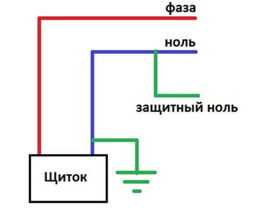
The diagram below repeats the previously stated principle of operation and the use of a protective grounding system.
The purpose of such a device is to quickly disconnect faulty electrical equipment from power, thereby neutralizing the damaging effect of electric current when a person touches a faulty device.
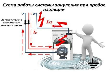
The operation scheme of the grounding system in case of insulation breakdown is shown below:
Discover, what is the difference between grounding and groundingYou can from our article!
Application area
Protective grounding is used in three-phase AC networks and single-phase AC and DC networks, the voltage level of which is up to 1000 V.
If the electric network is three-phase alternating current and the voltage level is 660 / 380V, 380 / 220V or 220 / 127V, then the neutral conductor is grounded - a TN type network.
If the network is single-phase alternating current, then protective grounding is applied provided that the network outlet is grounded.
If the network is single-phase direct current, then protective grounding is used if the midpoint of the source of electrical energy is grounded.
Protective grounding can be performed both with the help of PE conductors, and with the help of a combined PEN conductor. The use of this or that type of protective grounding depends on which grounding system is used in the electrical installation and what size the cross-sectional area of the power cables is.
According to clause 1.7.131 of the PUE, the functionality of the zero protective and zero working conductors can be combined, provided that they are used in multiphase circuits in the TN system and are laid stationary. In this case, the requirements for ensuring the cross-sectional area of the conductors made of different materials must be observed. The conductors of copper cables must have a cross-sectional area of at least 10 mm2, veins of aluminum cables - not less than 16 mm2.
Clause 1.7.132 PUE prohibits combining the functionality of zero protective and zero working conductors in single-phase and direct current circuits. For protective grounding, a separate third conductor is used - the exception is the branch from the overhead line with a voltage of up to 1 kV to single-phase electricity consumers.
Appointment
Protective grounding is used as protection against electric shock during the operation of electrical equipment for various purposes - domestic, industrial.
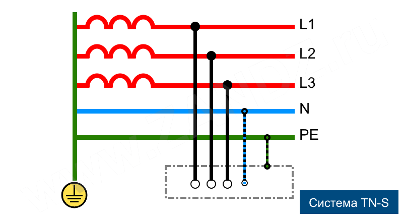
In the figure above, the neutral protective conductor of the TN-S system is labeled PE. A conductive circuit is shown connecting open conductive surfaces and a grounded neutral point on a power source in a three-phase network. This diagram reflects the purpose of the protective neutral conductor when grounding the neutral protective conductor in the TN-S system when a separate protective conductor is used.
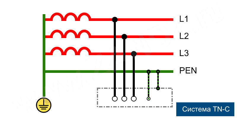
If grounding is applied in the system TN-C, then the scheme will look as follows:
In this case, the zero working and zero protective conductors are combined in one PEN conductor.
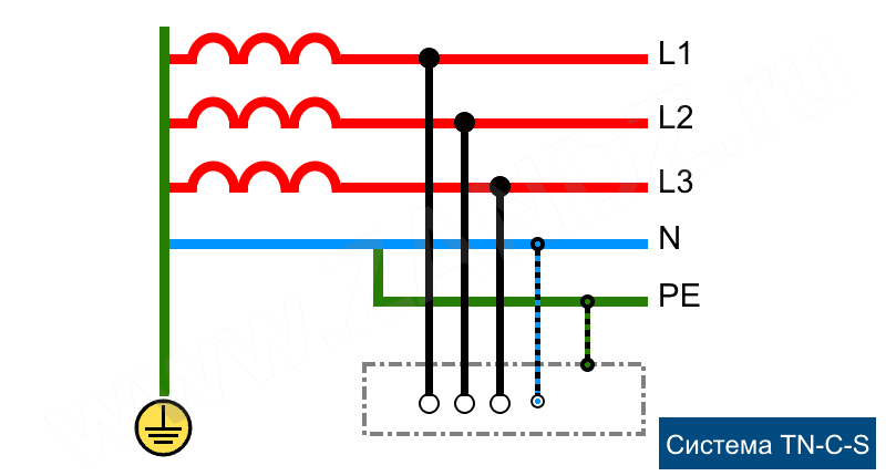
And in this three-phase network, the neutral protective conductor PE is separated from the PEN conductor at the input to the electrical installation:
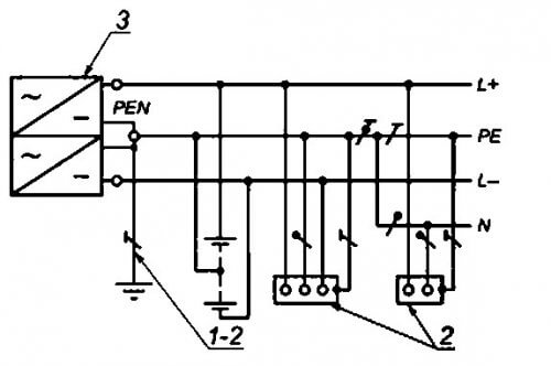
In a DC system, the midpoint of the source is grounded - Figure below:
1 - grounding neutral (midpoint) in the DC network; 2 - open conductive network elements; 3 - DC power supply.
In all cases considered, the protective neutral conductor performs a protective function, and in the case of combining with the working conductor N in the TN-C system, it also performs the function of the working neutral conductor.
We recommend finally watching a useful video on the topic:
So we examined the device, the principle of operation and the purpose of protective grounding. We hope you now understand how this system works and why it is needed.
It will be useful to read:

