What is contact bounce and how to fix it
Definition and essence of the problem in electronics
Contact bounce occurs when you press the button and switch, it occurs due to real vibrations of the contact plate when it is moved. Any switch is designed so that it has a movable and fixed contact. As the name implies, mobile is the one that is connected to the pusher or lever, which is already pressed by a person or mechanism during operation of the device.
Since the buttons have a mechanical device, how accurately they work out the presses depends on their quality. In this case, in any case, the phenomenon of bounce cannot be completely eliminated. What does he lead to?
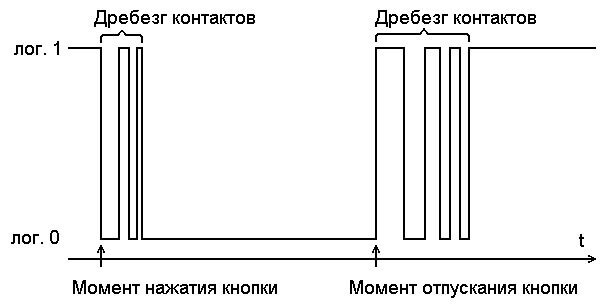
If a key controls some kind of electronic device with a digital input, for example, a microcontroller, logic element, etc., then its input will recognize as many clicks as there were impulses sent as a result of bounce.
An example of a waveform of contact bounce is shown in the figure below:
Effect elimination
To eliminate contact bounce, it is possible to use a hardware or software solution. Hardware solutions include:
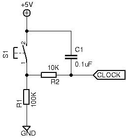
- Install capacitors parallel to the input. Then, the speed of the response to pressing may decrease if the capacity is too large and incomplete elimination of bounce when too small.
- The introduction of Schmidt triggers in the input circuit of the device. A more complex solution, which is difficult to implement during the finalization of an already finished product, but also more technological and perfect.
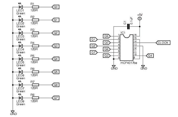
If we consider this phenomenon as an example of a shift register, then in this video its effect is clearly shown. After each button press, the next LED should light up.
The circuit for register and LEDs on the figure below:
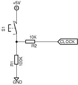
The button is connected as shown in the diagram:
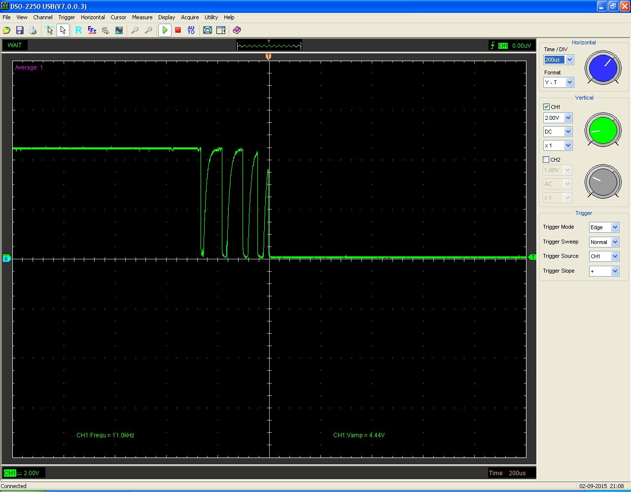
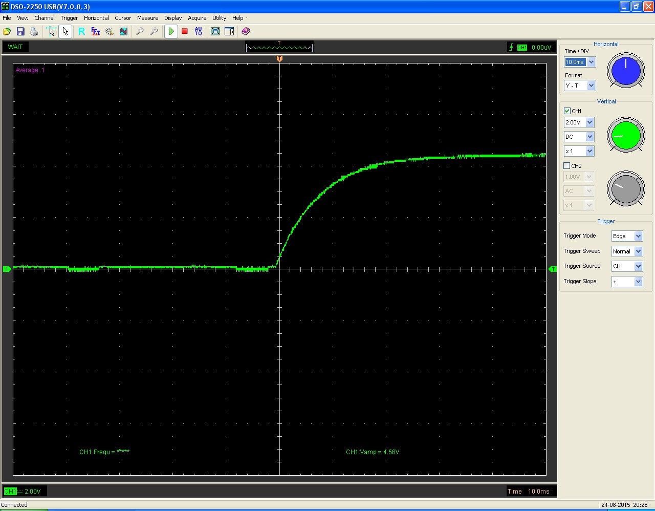
An example of a waveform of a signal with pronounced bounce:
By setting the capacitor to 1 μF parallel to the button to suppress it, we get a stable and accurate response:
Suppression Scheme:
And the front of the switching signal, as you can see, is really littered, but without any extra bursts.
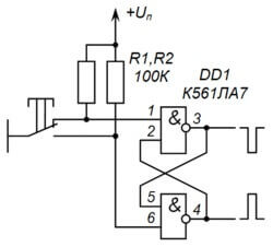
An alternative to such a solution to protecting against this effect, without collapsing the front and with high speed, is to use the Schmidt trigger. Its typical scheme is shown below:
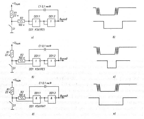
The following figure shows other options for logic gates to combat contact bounce:
In addition to hardware elimination, as was said, there is also a software way to solve this problem.It consists in writing code, the meaning of which is to read the signal changes, hold a certain time and read it again.
You can download an example of software chattering suppression of contacts in Arduino IDE by clicking on the link: bounce control code.
Rattle rattle
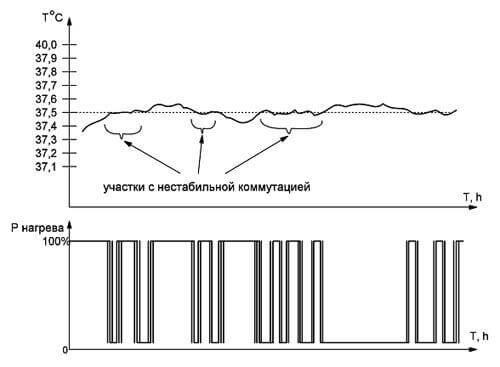
In addition to the rattling of buttons in digital electronic circuits, it also causes problems with the rattling of contacts in relay control circuits. These schemes include the twilight relay or various flow sensors, as well as temperature controllers. When the sensor generates a signal at the threshold of the device, an undefined state is obtained and the logic of the circuit turns it on and off. And when the relay is triggered, steady contact retention is not always observed, it starts to vibrate, turning on and off. The diagram below illustrates this problem by the example of a temperature controller:
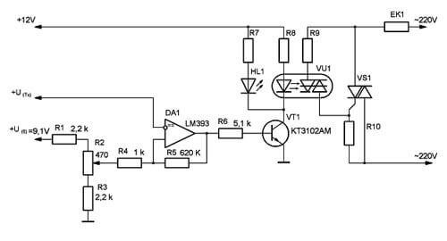
The solution to this problem is also the installation of a threshold element with a hysteresis loop in its transfer static characteristics, that is, a Schmidt trigger or a Comparator on an operational amplifier. The diagram below shows the initial version with the problem considered on the chart:
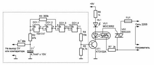
And it looks like a circuit with an addition in the form of an on-delay on logical elements 2I-NOT of a domestic K561LA7 chip:
Sometimes they cope with the same problem by installing a zener diode in signal circuits.
Similar to the rattling of buttons when the relay is turned on, its contacts can be reconnected several times. The phenomenon is dangerous because at this moment ignition and extinction of the arc occurs, which significantly reduces the service life of the device. Especially often this happens when the relay operates on alternating current.
All this is connected with the mechanical structure. reed switches, relays and other switches. Their contacts do not close immediately, but within fractions, units, or tens of milliseconds. To extend the life of the relay, check out the methods that we described in the article on why spark contacts.
We also recommend watching a good video on this topic:
Now you know what the bounce of relay contacts is and what methods of dealing with it are most effective. If you have questions, ask in the comments below the article!
Related materials:




Good afternoon. The problem is this, a water pump, a three-phase motor, switching on via a starter from a pressure sensor. When turned on, the starter does not work clearly, which leads to knocking out the machine at the power input. I think this is due to the bounce of the pressure sensor contacts. How can I fix this problem? Mechanical pressure sensor, starter and automatic 32 A. The motor, judging by the nameplate, consumes 13.5 A.
Hello, I propose replacing the machine with 75 amperes, because the starting current of the motor with direct start, and even under mechanical load (almost mechanical short circuit), can reach 5-7 times the rated current consumption of the motor. Make the current setting Iust - 1.15.