Replacing and connecting a three-gang switch with a socket
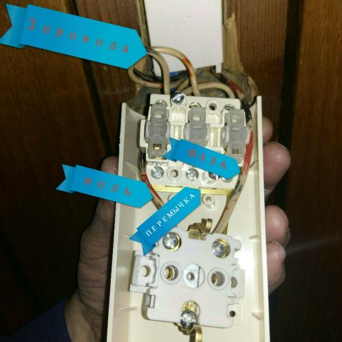
I decided to change the three-key block, I kind of connected the wires as in the old block, but the light does not turn on. Five wires, three connected to the keys, zero to the outlet. In this block, a jumper from the metal plate on the lower terminals of the keys and from it there is a strip to the outlet. I connected a phase under this terminal, as I think. I checked with a screwdriver on all the terminals there is voltage, except for zero. But the switch does not work. What am I doing wrong?
“I checked with a screwdriver on all the terminals there is voltage except zero” - checked how? As I understand it, they turned on each key and is there voltage in this position? Can you measure the real voltage between zero and each “output” terminal with the keys on? Did you ring the switch itself? To understand the connection diagram and the purpose of the terminals, you need to at least ring them, i.e. which terminals are closed when the key is “turned on”. If you believe how you signed everything in the picture, then the connection is correct. The phase goes from the outlet and is distributed through the bus to each of the keys of the switch - everything should be “as it should”. But while I was writing this, I had a question “how was it connected before?” Was the switch at zero? For fun, can you swap the phase with zero?


