A simple explanation of the gimlet rule
Name explanation
Most people remember the mention of this from the course of physics, namely the section of electrodynamics. This happened with good reason, because this mnemonics is often given to students to simplify the understanding of the material. In fact, the gimlet rule is applied both in electricity, to determine the direction of the magnetic field, and in other sections, for example, to determine the angular velocity.
By a gimlet is meant a tool for drilling holes of small diameter in soft materials, for a modern person it will be more usual to give a corkscrew for an example.
Important! It is assumed that the gimlet, screw or corkscrew has a right-hand thread, that is, the direction of its rotation, when twisted, clockwise, i.e. to the right.
The video below provides a complete statement of the gimlet rule, be sure to look to understand the whole point:
How is the magnetic field connected with the gimlet and hands
In problems in physics, in the study of electrical quantities, one often encounters the need to find the direction of the current along the magnetic induction vector and vice versa. Also, these skills will be required in solving complex problems and calculations related to the magnetic field of systems.
Before starting to consider the rules, I want to remind you that the current flows from a point with a large potential to a point with a smaller one. It can be said simply - the current flows from plus to minus.
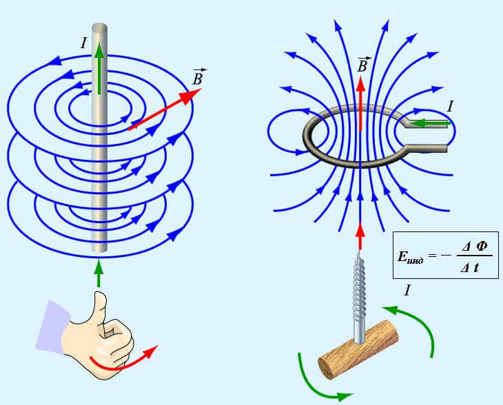
The gimlet rule has the following meaning: when screwing the gimlet tip along the current direction, the handle will rotate in the direction of vector B (vector of magnetic induction lines).
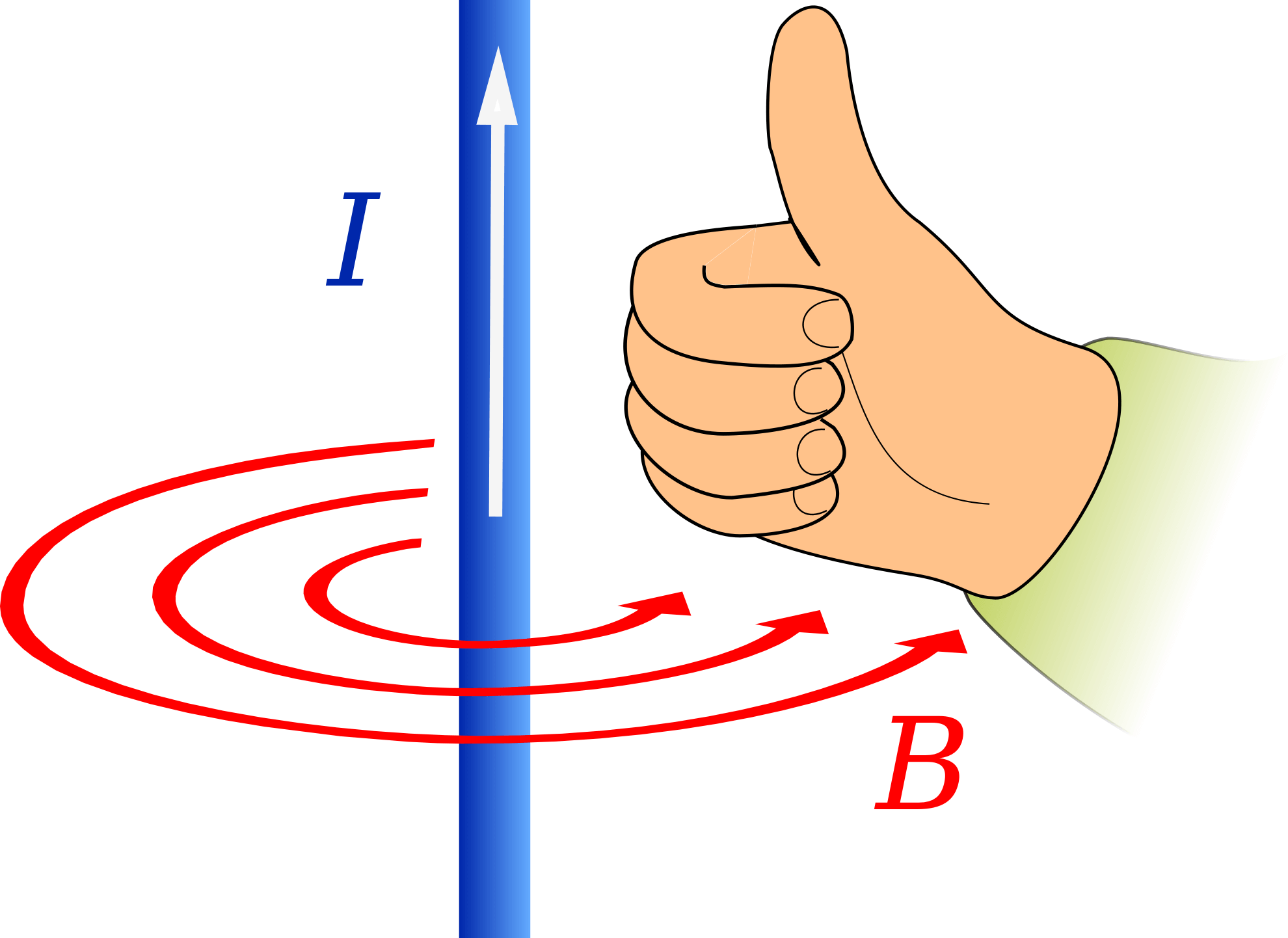
The right-hand rule works like this:
Place your thumb as if you were showing “class!”, Then turn your hand so that the direction of the current and the finger coincide. Then the remaining four fingers coincide with the magnetic field vector.
Visual analysis of the rule of the right hand:
To see this more clearly, conduct an experiment - sprinkle metal shavings on paper, make a hole in the sheet and thread the wire, after applying current to it, you will see that the shavings are grouped in concentric circles.
Magnetic field in the solenoid
All of the above is true for a rectilinear conductor, but what if the conductor is wound into a coil?
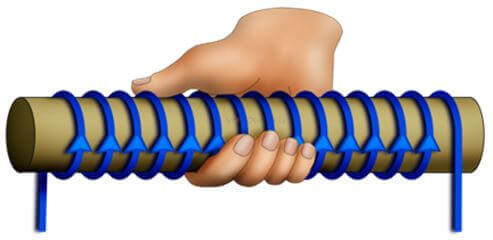
We already know that when a current flows around a conductor, a magnetic field is created, a coil is a wire rolled into rings around a core or mandrel many times. The magnetic field in this case is amplified. A solenoid and a coil are basically the same thing. The main feature is that the lines of the magnetic field pass in the same way as in the situation with a permanent magnet. The solenoid is a controlled analogue of the latter.
The right hand rule for a solenoid (coil) will help us determine the direction of the magnetic field. If you take the coil in your hand so that four fingers look in the direction of current flow, then the thumb will point to the vector B in the middle of the coil.
If you twist a gimlet along the turns, again in the direction of the current, i.e. from the “+” terminal to the “-” terminal of the solenoid, then the sharp end and the direction of motion are the magnetic induction vector.
In simple words - where you turn the gimlet, the lines of the magnetic field go out there. The same is true for one turn (circular conductor)
Determination of current direction by a driller
If you know the direction of the vector B - magnetic induction, you can easily apply this rule. Mentally move the gimlet along the direction of the field in the coil with the sharp part forward, respectively, clockwise rotation along the axis of movement will show where the current flows.
If the conductor is straight - rotate the corkscrew handle along the indicated vector, so that this movement is clockwise. Knowing that it has a right-hand thread, the direction in which it is screwed in coincides with the current.
What is connected with the left hand
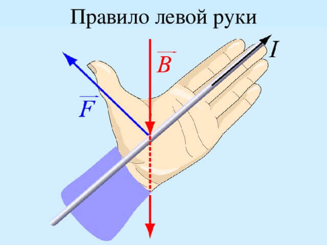
Do not confuse the gimlet and the rule of the left hand, it is necessary to determine the force acting on the conductor. The straightened palm of the left hand is located along the conductor. The fingers show the direction of current I. The field lines pass through the open palm. The thumb coincides with the force vector - this is the meaning of the rule of the left hand. This force is called the power of Ampere.
You can apply this rule to a separate charged particle and determine the direction of 2 forces:
- Lorentz.
- Ampere.
Imagine a positively charged particle moving in a magnetic field. The lines of the magnetic induction vector are perpendicular to the direction of its motion. You need to put the open left palm with your fingers in the direction of charge movement, vector B should penetrate the palm, then the thumb will indicate the direction of the vector Fa. If the particle is negative, the fingers look against the course of the charge.
If at some point you did not understand, the video clearly shows how to use the rule of the left hand:
It's important to know! If you have a body and a force acts on it, which tends to turn it, turn the screw in this direction, and you will determine where the moment of force is directed. If we are talking about angular velocity, then this is the case: when the corkscrew rotates in the same direction as the body rotates, it will be screwed in the direction of angular velocity.
findings
To master these methods of determining the direction of forces and fields is very simple. Such mnemonic rules in electricity greatly facilitate the tasks of schoolchildren and students. Even a full teapot will figure it out with a gimlet if he opens the wine with a corkscrew at least once. The main thing is not to forget where the current flows. I repeat that the use of a gimlet and a right hand are most often successfully used in electrical engineering.
Finally, we recommend watching a video, thanks to which you can understand by example what a gimlet rule is and how to apply it in practice:
Surely you do not know:




A very good explanation, and I suggest how you can make it even better! I suggest adding + and - icons to the existing pictures in the current picture; and the letters N S - where the magnetic induction vector is drawn - to complete the picture!