How to make a do-it-yourself antenna for digital television
The difference between analog and digital TV
Conventional, analogue TV broadcasts television programs in the meter and decimeter ranges. For terrestrial TV, 12 channels of the meter range and 49 channels of the decimeter range are used (from the 21st to the 69th channel). Each channel occupies a frequency band of 8 MHz.
The digital channel has similar parameters. Therefore, the main confusion lies in the concepts of “channel” and “program”. For an analog signal, these concepts are identical. But when using discrete broadcasting in one channel, several tens of television programs can be transmitted. The digital channel is called "multiplex."
Digital broadcasting is sometimes called discrete.
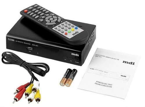
Television broadcasting is carried out in the DVB-T2 standard. At the same time, the multiplex can include from 10 channels, in the HD quality standard. Additionally, the multiplex includes several radio programs. Television, where a digital signal is used, requires the use of special decoding devices, which can be external or built-in to the TV.
Features of digital television
Modern discrete television broadcasting is capable of transmitting a picture with high quality. But it should be borne in mind that with a low signal level or poor-quality antenna (which is equivalent), the decoder of the television receiver is not able to perform decoding and the image will be completely absent. This is the main feature of digital broadcasting in contrast to analog. In analog it was possible to receive weak signals and the image differed only in the presence of interference of varying intensity.
Also, with poor reception quality, all multiplex programs are completely missing. In this regard, an improperly manufactured antenna does not allow tuning to the transmitting station.
How to make a homemade antenna
Features of digital broadcasting do not put forward special requirements for the quality of antenna manufacturing. Designing and manufacturing at home requires strict adherence to the geometric dimensions of the elements and the accuracy of the assembly.
The main difficulty lies in the choice of design and element size calculations, since any antenna has the following properties:
- the greater the gain of the antenna, the narrower its frequency range (the number of received channels);
- gain increases with narrower radiation patterns.
The conclusions are as follows - there is no universal design that has a wide bandwidth and high gain. Any antenna is a compromise between the parameters.
A narrow directional band requires accurate orientation to the TV program transmitter, but at the same time it has high noise immunity.
Assembling a decimeter antenna with your own hands, it is important to strictly observe the geometric dimensions of the structure. Errors should not exceed a few millimeters, since at these frequencies the radio waves have a short length.
Inaccuracies in manufacturing lead to an expansion of the radiation pattern and a decrease in gain.
Receiver Types
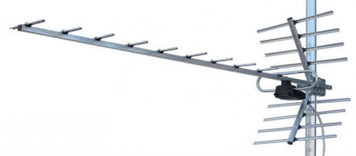
The highest gain and highest coefficient has a directional antenna "wave channel". Unfortunately, this design combines good performance with the narrowest frequency range. An ideal “wave channel” antenna has a maximum gain on only one frequency channel. The farther away the frequency of the remaining channels is, the lower the gain. Before you make such a device, you need to know the exact frequency of reception.
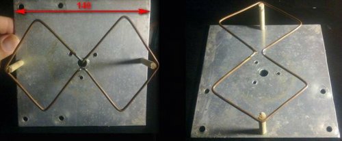
The most common design available for repetition at home is the Harchenko antenna or its variants. In the literature, the Harchenko antenna for receiving TV channels is also known as the figure eight or biquadrat.
With sufficient amplification, the figure eight allows you to confidently receive many channels. So, an antenna for 100 channels with your own hands is not a fairy tale. For example, if a television center broadcasts three multiplexes of thirty programs each, then there are already 90 in total. And since a simple Kharchenko antenna has a two-sided orientation, you can receive TV programs from another television center.
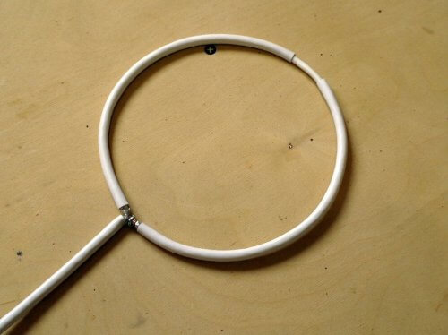
At short distances to the transmitting center, the indoor antenna can be made of a television cable.
The manufacturing technology of this design is as follows:
- At the end of the cable, insulation is removed from the braid and central core, which are then twisted together.
- At a distance equal to the wavelength of the received channel (calculation of the wavelength will be given below), insulation is removed before braiding.
- In the middle between the end of the cable and the bare braid, the outer insulation is removed and the braid is completely cut.
- The cable is bent into a ring and the twisted end and the bare braid are connected together.
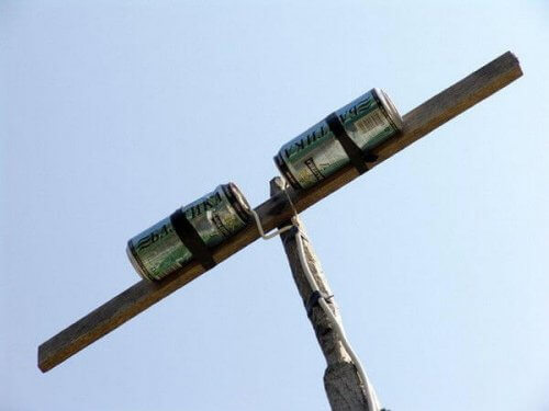
If necessary, for a TV, for example, in the country, it is not difficult to make a design for receiving TV from beer cans in 15 minutes. How it looks is shown in the figure below. Banks should have reeds to each other. The ends of the television cable are attached to the tongues. The distance between the ends of the cans to which the wire is attached should be 50-75 mm.
A rather low gain and weak directional properties pay off with a wide passband. Therefore, an antenna with 20 channels has minimal cost both financially and in time.
An example of how to make and upgrade the antenna you will see in the video below.
How to make a biquadrat on two frequencies
The main element of the device is a copper wire, with a diameter of 3-5 mm. It is not recommended to take thinner ones, because wind loads and precipitation act on the outdoor antenna, and a thicker one will require recalculation of geometric dimensions.
The calculations are based on the frequencies of channels (multiplexes). How to make a calculation? The signal frequency must be converted to wavelength using the formula:
λ = 300 / f,
where f is the signal frequency in megahertz.
The wavelength is calculated for each channel, and for further calculations take the average value.
The side length of the square is a quarter of the average wavelength.
Channel numbers and, accordingly, their frequencies vary in each region. This is done to reduce mutual interference.The correspondence tables of the channel number and frequency are in the public domain. Typically, the tables show the values of the upper and lower frequencies. For calculations, the average value is taken. As an example, consider the calculation of the antenna for digital channels (abbreviated TCEs) No. 32 and 36.
In accordance with the table, the channel frequencies are:
- 32 channel - 558 - 566 MHz;
- 36 channel - 590 - 598 MHz.
Channel frequency values for calculation:
- 32 channel - 562 MHz;
- 36 channel - 594 MHz.
Wavelength:
- 32 channel - 0.53 m;
- 36 channel - 0.50 m.
The average wavelength for calculating a two-channel antenna will be 0.515 m (51.5 cm).
Before you make the antenna, the wire must be carefully aligned. If it is covered with insulation (HB or fiberglass), it must be removed. Please note that a homemade antenna is made from a single piece of wire.
The side length of the square of the Kharenko antenna is ¼ wavelength. For the above example, this will be 12.9 cm
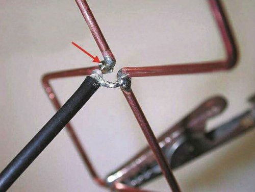
In the corners of the squares, the wire bends at an angle of 90 g. At the places where the coaxial cable is connected, the distance between the elements is 10-15 mm.
The cable is cut using this technology:
- At the end of the cable, outer insulation is removed to a length of 50 mm.
- The braid is carefully untwisted and twisted into a flagellum.
- At a distance of 40 mm from the end of the cable, the inner insulation is cut and the central core is released.
The finished eight through insulating racks is attached to a reflector - a reflector from a metal plate. This achieves the following:
- one-way orientation;
- increased noise immunity;
- gain increase.
The size of the reflector should be slightly larger than the butterfly in height and width. The distance from the wire to the reflector is 1/7 of the average wavelength of the signal, for our case it is 51.5 / 7 = 7.35 cm.
Antenna for an old TV
For modern and old TVs, the principle of reception is exactly the same and the antennas for them do not differ. The difference is only in the presence and absence of a built-in T2 decoder.
Even a carefully crafted antenna will not allow you to watch digital terrestrial television if there is no set-top box or built-in decoder to decode the digital signal. With a digital tuner (set-top box), even using the antenna of the simplest design of beer cans, you can receive a digital signal for free in a private house, cottage or apartment on a TV of any year of production.
In areas where the signal is weak, to show good, it is advisable to supplement the device with a power amplifier. A powerful antenna can be used on 2 TVs, and if they are modern, they can be used without a prefix.
Now you know how to make an antenna for your own digital TV. We hope our instructions with calculations helped to make a suitable option for your conditions!

