What is a voltage regulator and what is it for?
Definition
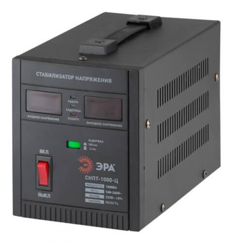
A voltage stabilizer (CH) is a device designed to convert an unstable input voltage from an electrical network: underestimated, overstated, or with periodic surges, to a stable in magnitude output device and electrical appliances connected to it.
We rephrase it for dummies: the stabilizer makes it so that for the devices connected to it, the voltage is always the same and close to 220V, regardless of how it goes to its input: 180, 190, 240, 250 Volts or even floats.
Note that 220V or 240V is the standard value. But in some countries near and far abroad it may be different, for example 110V. Accordingly, “our” stabilizers will not work there.
Stabilizers are different species: both for work in direct current circuits (linear and pulse, parallel and serial types), and for work in alternating current circuits. The latter are often called “mains voltage stabilizers” or simply “220V stabilizers”. In simple terms, such stabilizers are connected to the mains, and consumers are already connecting to it.
In everyday life, SN is used to protect both individual devices, for example, for a refrigerator or a computer, and to protect the entire house, in this case a powerful stabilizer is installed on the input.
Classification
The design of stabilizers depends on the physical principles on which they operate. In this regard, they are divided into:
- electromechanical;
- ferroresonance;
- inverter;
- semiconductor;
- relay.
By the number of phases can be single-phase and three-phase. A wide range of capacities allows the production of stabilizers for both home and small household appliances:
- for the tv;
- for gas boiler;
- for the fridge.
So for large objects:
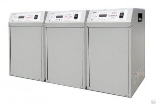
- industrial units
- workshops, buildings.
Stabilizers are quite energy efficient. Electricity consumption is from 2 to 5%. Some stabilizing devices may have additional protections:
- from surge;
- from overloads;
- from short circuits;
- from frequency differences.
Operating principle
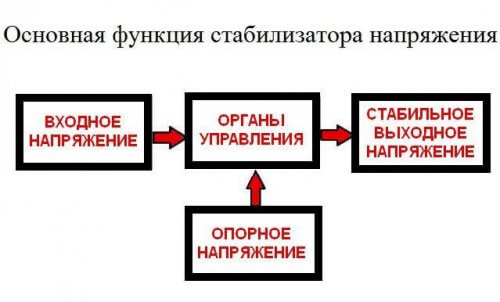
Voltage stabilizers are of various types, each of which differs in the principle of regulation. We will consider these differences below.If we generalize the principle of operation and the structure of all types, then the mains voltage stabilizer consists of 2 main parts:
- Control system - monitors the input voltage level and gives the command of the power unit to increase or decrease it, so that the output will produce stable 220V within the specified error (regulation accuracy). This error lies within 5-10% and is different for each device.
- The power part - in servo (or servomotor), relay and electronic (triac) - is an autotransformer, with which the input voltage rises or falls to a normal level, and in inverter stabilizers, or as they are also called "with double conversion", an inverter is used . This is a device that consists of a generator (PWM controller), a transformer and power switches (transistors) that pass or disconnect current through the primary winding of the transformer, forming the output voltage of the desired shape, frequency and, most importantly, magnitude.
If the input voltage is normal, then some stabilizer models have a “bypass” or “transit” function, when the input voltage is simply applied to the output until it leaves the specified range. For example, bypass will be switched on from 215 to 225 volts, and in case of large fluctuations, for example, with a drawdown of up to 205-210V, the control system will switch the circuit to the power part and begin adjustment, increase the voltage and the output will already be stable 220V with a given error .
Smooth and most accurate adjustment of the output voltage for inverter MVs, in second place - servo-drives, and for relay and electronic ones, the adjustment is stepwise, and the accuracy depends on the number of stages. As mentioned above, lies within 10%, more often around 5%.
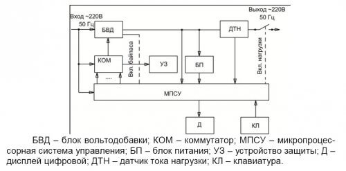
In addition to the above two parts, the 220V voltage regulator also has a protection unit, as well as a secondary power source for the control system circuits, the same protections and other functional elements. The general device clearly shows the picture below:
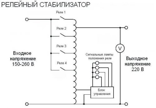
At the same time, the scheme of work in its simplest form looks like this:
We will briefly review how voltage stabilizers of the main types work.
Relay
In the relay stabilizer, regulation occurs by switching the relay. These relays close certain transformer contacts, increasing or decreasing the output voltage.
The controlling body is an electronic microcircuit. Elements on it compare the reference and line voltage. If there is a mismatch, a signal is given to the switching relays to connect the increasing or decreasing windings of the autotransformer.
Relay SNs usually regulate electricity within ± 15% with an accuracy of output from ± 5% to ± 10%.
Advantages of relay stabilizers:
- cheapness;
- compactness.
Disadvantages:
- slow response to voltage fluctuations;
- short service life;
- low reliability;
- when switching, short-term power off of devices is possible;
- unable to withstand overvoltages;
- noise, clicks when switching.
Servo drive
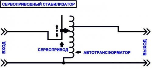
The main elements of servo stabilizers are an autotransformer and a servo motor. If the voltage deviates from the norm, the controller gives a signal to the servomotor, which switches the necessary windings of the autotransformer. As a result of the use of such a system, smooth regulation and accuracy of up to 1% of the total range are ensured.
In the servo drive SN, one end of the primary winding of the transformer is connected to a rigid branch of the autotransformer, and the second end of the primary winding is connected to a movable contact (graphite brush), which is moved by a servomotor. One terminal of the secondary winding of the transformer is connected to the input power source, and the second terminal is connected to the output of the voltage regulator.
The control board compares the input and reference voltage. In case of any deviations from the set, the servo motor comes into operation.He moves the brush along the branches of the autotransformer. The servomotor will continue to run until the difference between the reference and output voltage becomes zero. The whole process, from the supply of poor-quality electricity to the output of a stabilized current, takes tens of milliseconds and is limited by the speed of the brush moving with a servo drive.
Servo-driven voltage stabilizers are produced in various designs.
- Single phase. Consist of one autotransformer and one servo drive.
- Three phase. They are divided into two types. Balanced - have three transformers and one servo drive and one control circuit. Regulation is carried out on all three phases simultaneously. Used to protect three-phase electrical apparatus, machine tools, appliances. Unbalanced - they have three autotransformers, three servomotors and three control circuits. That is, stabilization occurs in each phase, independently of each other. Scope: protection of electrical equipment of buildings, workshops, industrial facilities.
Advantages of servo-stabilizing devices:
- performance;
- high accuracy of stabilization;
- high reliability;
- resistance to overvoltage;
Disadvantages:
- need periodic maintenance;
- require minimal device setup skills.
Inverter
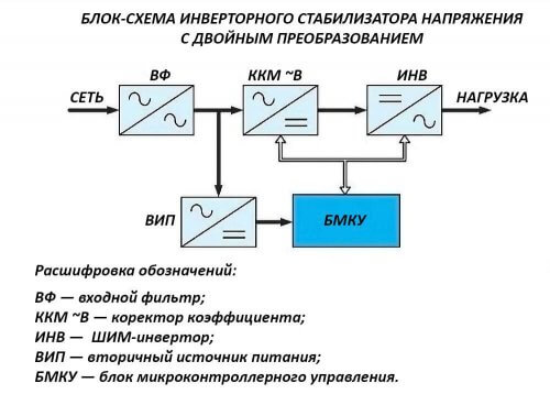
The main difference between this type of SN is the absence of moving parts and a transformer. Voltage regulation is carried out by the double conversion method. At the first stage, the input alternating current is rectified and passes through a ripple filter, consisting of capacitor. After that, the rectified current flows to the inverter, where it is again converted into alternating current and supplied to the load. In this case, the output voltage is stable both in magnitude and in frequency.
In the next video, you will learn about the principle of operation of one of the options for implementing a voltage converter from 12V DC to 220V AC. Which differs from the inverter voltage stabilizer in the first place by the input voltage, otherwise the principle of operation is largely similar and the video will allow you to understand how this type of device works:
Advantages:
- performance (the highest of those listed);
- large range of adjustable voltage (from 115 to 300V);
- high coefficient of performance (more than 90%);
- silent work;
- small dimensions;
- smooth regulation.
Disadvantages:
- reduction of the regulation range with increasing load;
- high price.
So we examined how the voltage regulator works, why it is needed and where it is used. We hope the information provided was useful and interesting for you!
Related materials:

