What is an inductor and why is it needed
Definition and principle of action
An inductor is a coil of an insulated conductor wound into a spiral or other form. Main features and properties: high inductance at low capacitance and active resistance.
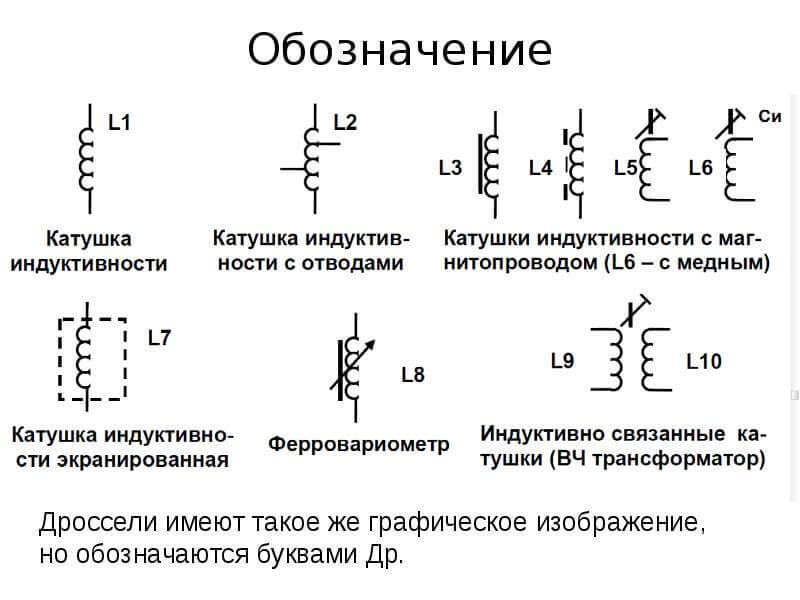
It stores energy in a magnetic field. In the figure below you see its conditional graphic designation on the diagram (UGO) in different types and functional purposes.
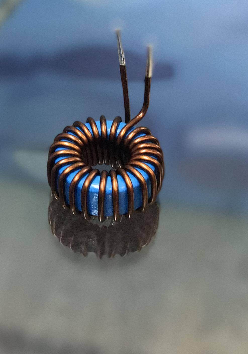
It can be with and without a core. In this case, the inductance with the core will be many times greater than if it is not. The inductance value also depends on the material from which the core is made. The core can be solid or open (with a gap).
Recall one of the laws of switching:
The current in the inductance cannot change instantly.
This means that an inductor is a kind of inertial element in an electrical circuit (reactance).
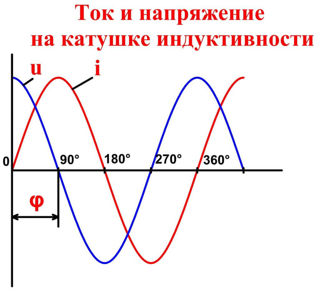
Let's talk, how does this device work? The larger the inductance, the more the current change will lag behind the voltage change, and in AC circuits the current phase will lag behind the voltage phase.
This is the principle of operation of inductance coils - the accumulation of energy and the delay of the front of the rise of current in the circuit.
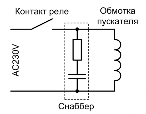
The following fact also follows from this: when a circuit breaks with a high inductance, the voltage on the key rises and forms arcif the key is semiconductor - it breaks down. To combat this, snubber chains are used, most often from resistor and capacitorinstalled parallel to the key.
Types and types of coils
Depending on the application and frequency of the circuit, coil design may vary.
The frequency can be divided into:
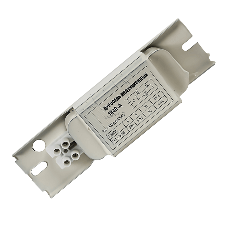
- Low frequency. An example is a fluorescent lamp choke, a transformer (each winding is an inductor), a reactor, electromagnetic interference filters. Cores are most often made of electrical steel for alternating current circuits made of sheets (lined core).
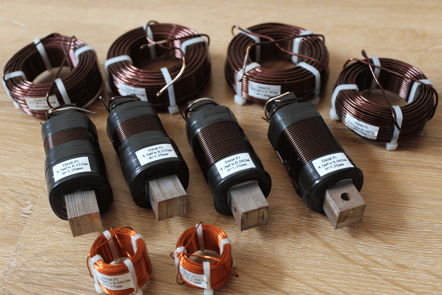
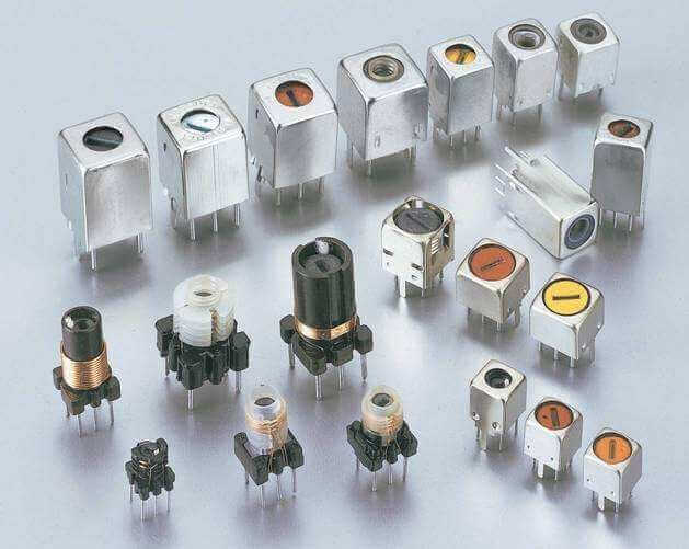
- High frequency. For example, loop coils of radio receivers, coupling coils of signal amplifiers, storage and smoothing chokes of switching power supplies. Their core is usually made of ferrite.
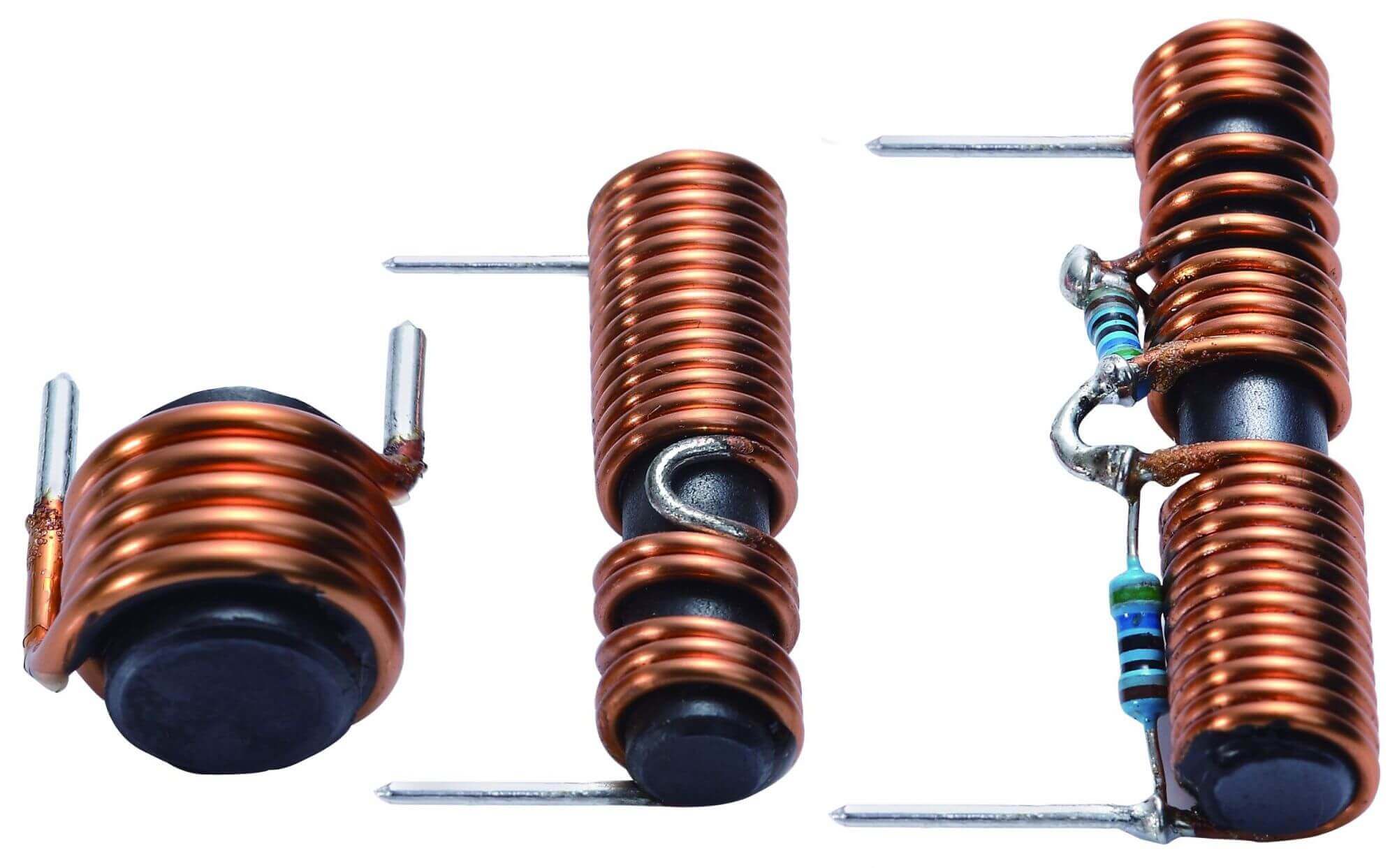
The design differs depending on the characteristics of the coil, for example, the winding can be single-layer and multi-layer, wound round to round or in increments.The pitch between the turns can be constant or progressive (varying along the length of the coil). The winding method and design affect the final dimensions of the product.
We should also talk about how the coil with variable inductance is arranged, they are also called variometers. In practice, you can find different solutions:
- The core can move relative to the winding.
- Two windings are located on the same core and connected in series, when moving, the mutual induction and inductive coupling change.
- The turns themselves for adjusting the circuit can be moved apart or taper closer to each other (the denser the winding, the greater the inductance).
Etc. In this case, the moving part is called the rotor, and the fixed part is called the stator.
The winding method is also different, for example, filters with counter winding suppress network interference, and wound in one direction (matched winding) suppress differential interference.
What are needed and what are
Depending on where the inductor is used and its functional features, it can be called differently: chokes, solenoids, etc. Let's look at what are the inductors and their scope.
Chokes. Usually so-called current limiting devices, scope:
- In ballasts for ignition and power of discharge lamps.
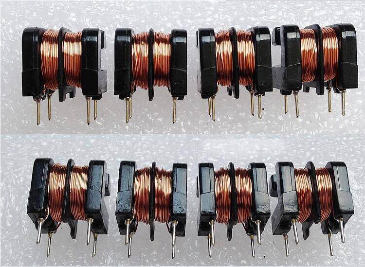
- To filter interference. In power supplies - an electromagnetic interference filter with a double inductor at the input of a computer PSU, is shown in the photo below. Also used in acoustic equipment and others.
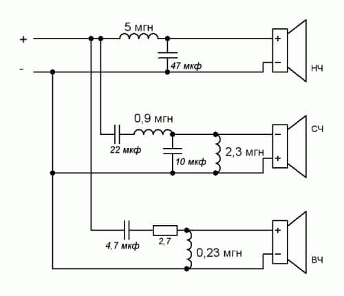
- For filtering specific frequencies or frequency bands, for example, in speaker systems (to separate frequencies according to the respective speakers).
- The basis of pulse converters is energy storage.
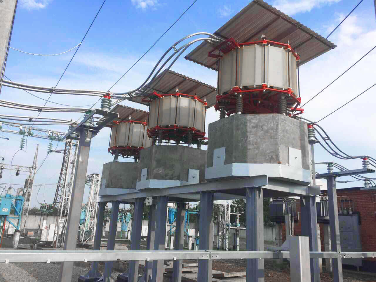
Current-limiting reactors - are used to limit short circuit currents on power lines.
Note: Inductors and reactors should have low resistance to reduce their heating and losses.
Loop Inductors Used in conjunction with a capacitor in the oscillatory circuit. The resonant frequency is selected according to the frequency of reception or transmission in radio communications. They should have high quality factor.
Variometers. As said, these are customizable or variable inductors. Most often used in the same oscillatory circuits to fine tune the resonance frequency.
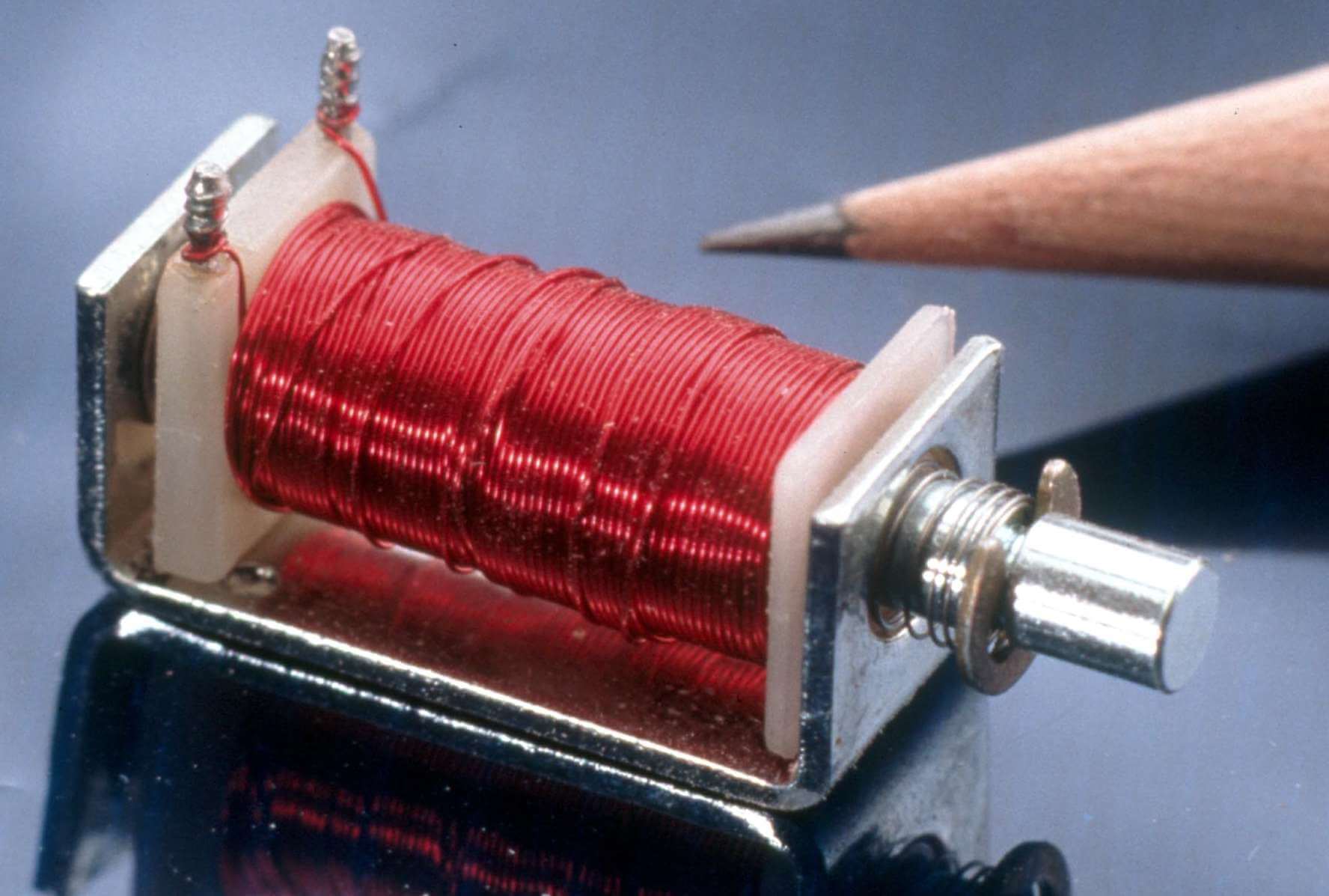
Solenoid - the so-called coil, the length of which is much larger than the diameter. Thus, a uniform magnetic field is formed inside the solenoid. Most often, solenoids are used to perform mechanical work - translational motion. Such products are also called electromagnets.
Consider where the solenoids are used.
This can be an activator of the lock in a car, the rod of which is retracted after applying a voltage to the solenoid, and a bell, and various actuators, electromechanical devices such as valves, lifting magnets in the metallurgical industry.
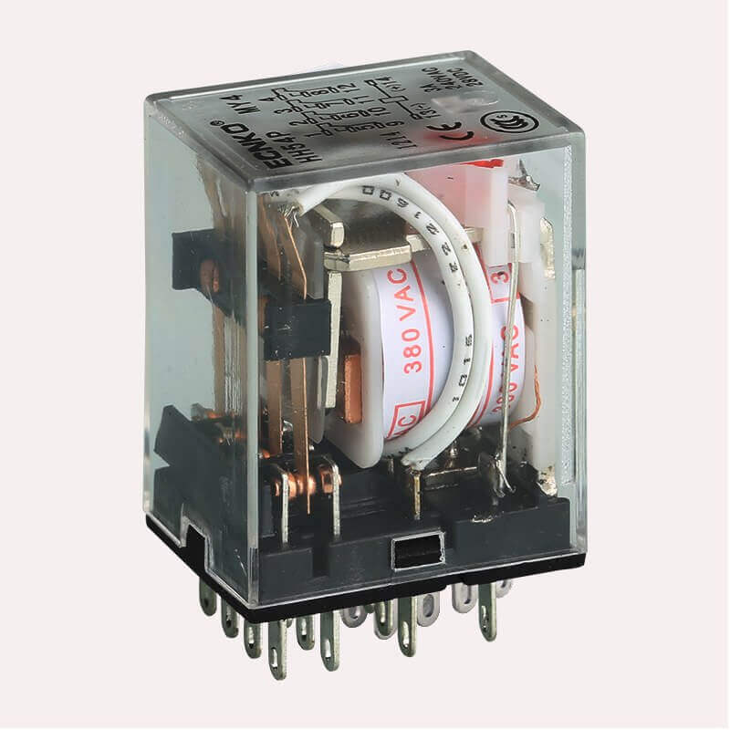
In the relay contactors and starters the solenoid also acts as an electromagnet to drive power contacts. But in this case, it is often called simply a coil or winding of a relay (starter, contactor, respectively), as it looks, on the example of a small relay you see below.
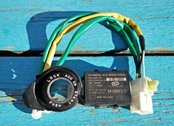
Frame and ring antennas. Their purpose is the transmission of radio signals. Used in car immobilizers, metal detectors and for wireless communications.
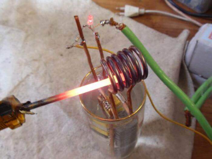
Induction heaters, then it is called an inductor, instead of the core, a heated body (usually metal) is placed.
main parameters
The main characteristics of the inductance coil include:
- Inductance.
- Current strength (to select a suitable element for repair and design, this must be taken into account).
- Loss resistance (in wires, in the core, in dielectric).
- Q-factor is the ratio of reactance to active.
- Spurious capacitance (capacitance between turns, in simple terms).
- Temperature coefficient of inductance - change in inductance during heating or cooling of an element.
- Temperature coefficient of quality factor.
Marking
To indicate the rating of the inductance coil, letter or color marking is used. There are two types of lettering.
- Designation in microgenry.
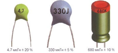
- Designation by a set of letters and numbers. The letter r is used instead of the decimal point, the letter at the end of the designation indicates the tolerance: D = ± 0.3 nH; J = ± 5%; K = ± 10%; M = ± 20%.

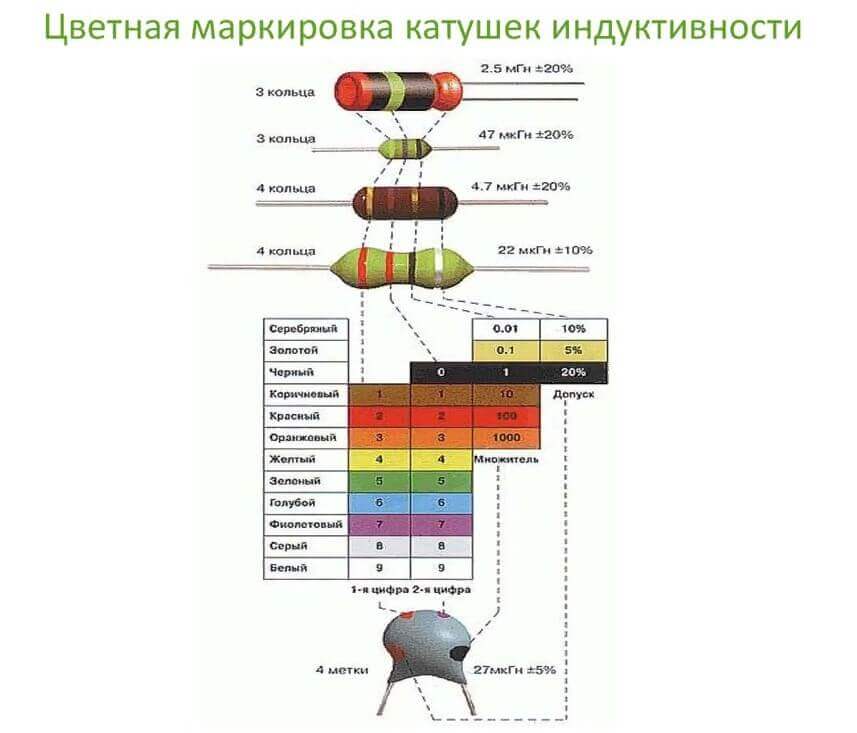
Color coding can be recognized similarly to that of resistors. Use the table to decode the color bars or rings on the element. The first ring is sometimes made wider than the rest.
This is where we finish considering what an inductance coil is, what it consists of and why it is needed. Finally, we recommend watching a useful video on the topic of the article:
Related materials:

