What is portable grounding and what is it for?
Device
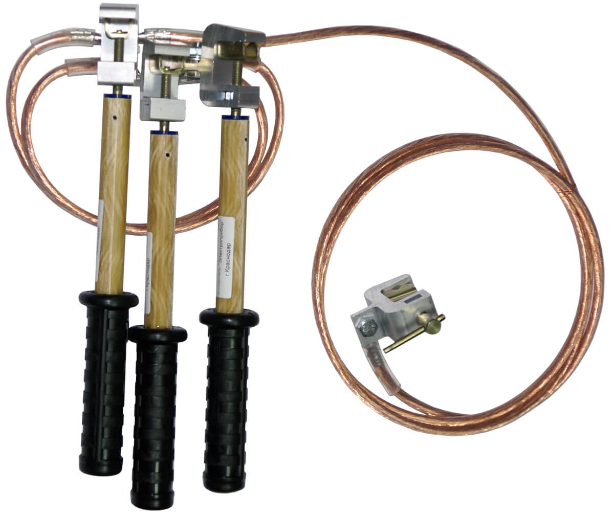
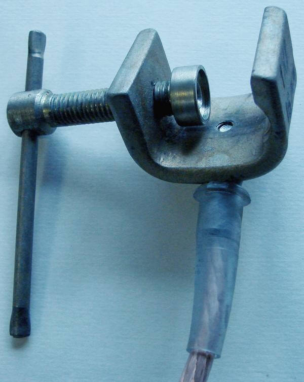
It is made of a flexible, copper cable, without braiding, with devices for fastening like a clamp with insulating handles for interrupting phases and connecting to the grounding bus. There are both for three-phase devices, structurally combining four grounding conductors into one device, and separately to the ground bus and phase.
Portable ground looks like in the photo:

The design of the clamps allows their installation using special insulating rod. The conductors are combined in a three-phase ground electrode by crimping or welding, bolt connection is allowed, but the conductors must be tinned with refractory solder at the crimp site. Just soldering is not allowed, because short-circuit currents can warm up the connection and destroy the integrity of the device.
You can clearly see what portable grounding is and how to use it correctly, in the video tutorial below:
Requirements
The cable and mountings of the portable device must withstand short-circuit current and dynamic loads. Clips provide reliable contact, be heat-resistant. The core section for installations up to 1000 Volts is not less than 16 mm. Above 1000 volts, the core is not less than 25 mm.
At voltages higher than 6 kV, the core section will be 120 mm and higher, which is not practical and difficult. Therefore, it is allowed to install several groundings nearby, in total gaining the desired section.
It is forbidden to use a wire in insulation for grounding conductors since the insulating layer makes it difficult to detect damage to the conductor's wires and reducing the design cross-section in time, which can lead to burnout of the grounding conductor.
Section calculation
The required cross-section of the core can be calculated by a simplified formula:
S = (Iust √ tf) / 272
Where:
- Iust - steady-state short circuit current. AND;
- tf - fictitious time, sec;
When calculating the grounding for a switchgear of the same voltage, tf take the largest value of the response time of the protection relay of the electrical installation. In networks with a grounded neutral, the core section is calculated by the short-circuit current of one phase.
Installation and Removal Procedure
Installation is made on a de-energized section of live busbars from the side from which voltage can be supplied. Before installation pointer check the absence of voltage on the current-carrying tires, and then a portable grounding is installed. First of all, the clamps are attached to zero bus or a grounded design, and then alternately phase.
It is necessary to establish grounding using an insulated rod, using protective equipment, wearing bots and mittens, as shown in the picture:

If the site where the work is performed is separated by switching devices, or the tires are disassembled, grounding is imposed on both sides of the work site to prevent voltage pickup from a number of current-carrying busbars.
Installation of portable grounding is carried out from the floor or the ground, lifting to the equipment that has not yet been grounded is prohibited without repeated verification of the absence of voltage. Portable grounding is removed in the reverse order. First, the clamps are removed from the current-carrying tires, then the conductor is removed from the grounded element or the zero bus. Portable grounding must be removed using an insulated pole and protective equipment. After removing the jumpers, it is forbidden to touch the tires without protective equipment, since voltage can be induced on them.
The video examples below demonstrate how to install portable grounding:
Remember, work in electrical installations is carried out according to a work permit, accompanied by an observer, with briefing before starting work, in accordance with applicable safety instructions and technical operation rules.
That's all I wanted to tell you about what portable grounding is, how to install it and what requirements are presented to the conductor cross-section. We hope the information was useful and understandable to you.
It will be interesting to read:


electricians install p / z in the switchgear chamber without the use of PPE for protection from the arc, helmets without a protective visor.